
Standard CMOS low-noise high PSRR low drop-out regulator with new dynamic compensation

a voltage regulator and dynamic compensation technology, applied in the field of integrated circuits, can solve the problems of reducing the noise performance of the regulator, affecting the performance of the voltage regulator, and affecting the performance of the circuit structure, so as to improve the noise performance of the voltage regulator, improve the voltage regulator, and improve the effect of the voltage regulator

Inactive Publication Date: 2008-07-29
ATMEL CORP
View PDF18 Cites 37 Cited by
  • Summary
  • Abstract
  • Description
  • Claims
  • Application Information

AI Technical Summary

Benefits of technology

The solution provides a high open-loop gain, low noise, and high PSRR with reduced silicon area, maintaining stability and current efficiency without compromising noise or quiescent current performance, effectively addressing the limitations of prior art by ensuring the pole-zero doublet and unity gain frequency vary in proportion to the square root of the load current.

Problems solved by technology

Regulators of this type are preferentially fabricated in standard low-cost CMOS processes, making them difficult to realize with the required performance characteristics.
1. The current efficient buffer circuit requires NPN bipolar transistors to avoid creation of a parasitic pole at the output of an error amplifier within the circuit.
2. The structure based on the pole-zero doublet can be stabilized if the dc open-loop gain is relatively small (e.g., 50 dB for a high current load). However, since the dc value of the PSRR is proportional to the inverse of the open-loop gain of the regulator, the dc value of the PSRR for this design cannot exceed 50 dB.
3. The Miller compensation method creates an internal pole. To make the cutoff frequency of the PSRR as high as possible, the pole of the first stage has to be as high as possible. Thus, the PSRR performance of this circuit structure is compromised. The noise performance of the regulator is also reduced.
This makes the system transfer function second order and unstable.
It becomes difficult to maintain stability when large variations in current load IL are desired.

Method used


Image

  • Standard CMOS low-noise high PSRR low drop-out regulator with new dynamic compensation
  • Standard CMOS low-noise high PSRR low drop-out regulator with new dynamic compensation
  • Standard CMOS low-noise high PSRR low drop-out regulator with new dynamic compensation

Examples


Embodiment Construction

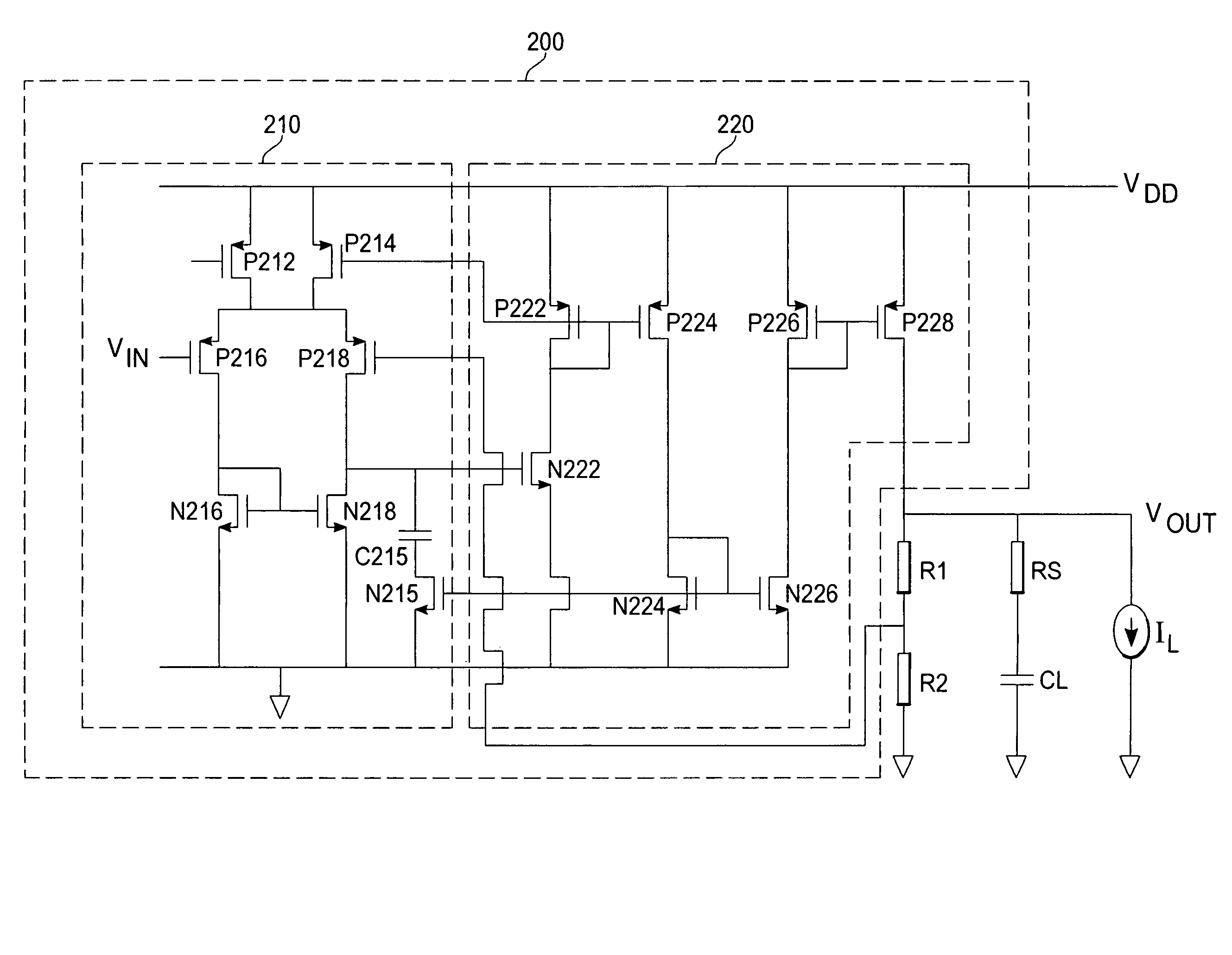
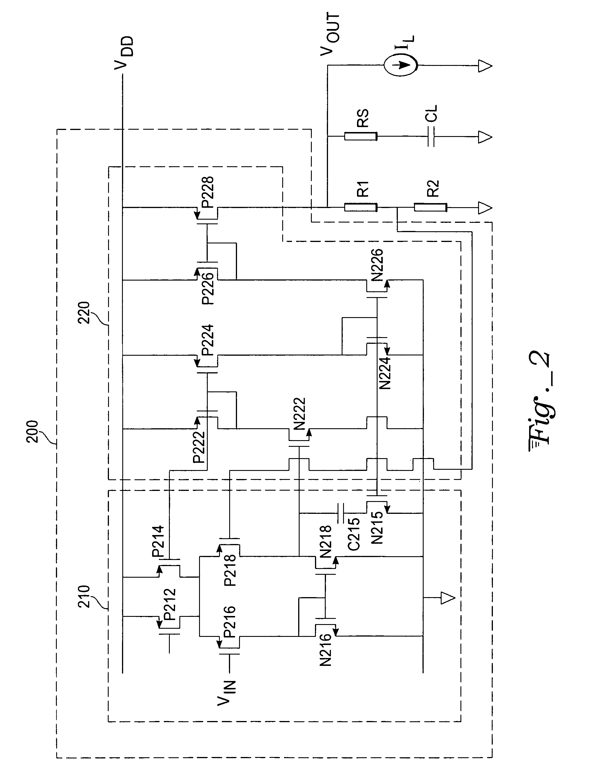
[0057]With reference to FIG. 2, exemplary regulator circuit 200 comprises a first amplifier stage 210 and a second amplifier stage 220. The first amplifier stage 210 comprises PMOS transistors P212, P214, P216, and P218. The first amplifier stage 210 further comprises a zero stabilizing capacitor C215, diode-connected NMOS transistor N216, resistor-like NMOS transistor N215 and NMOS transistor N218. The second amplifier stage 220 comprises diode-connected PMOS transistors P222 and P226, a PMOS transistor P224, a PMOS power transistor P228, a diode-connected NMOS transistor N224, and NMOS transistors N222 and N226.

[0058]The PMOS transistor P212 has its source terminal coupled to a first power supply potential VDD, its gate terminal coupled to a constant bias potential, and its drain terminal coupled to a drain terminal of PMOS transistor P214. The drain terminal of PMOS transistor P212 is further coupled to the source terminal of PMOS transistor P216 and to the source terminal of PMO...


PUM


Abstract

A voltage regulator circuit has a first amplifier stage with input and output terminals, a feedback terminal, a pole-inducing transistor, and a compensating network coupled to the output terminal. A second amplifier stage has an input coupled to the first amplifier output, first and second current mirrors, and a pass transistor.

Description

TECHNICAL FIELD[0001]The present invention is related to integrated circuits. More specifically, the present invention is an apparatus and method for a voltage regulator circuit.BACKGROUND ART[0002]Low drop-out (LDO) voltage regulators are implemented in a variety of circuit applications to provide regulated power supplies. Increased regulator performance is especially being demanded in mobile battery-operated products such as cellular phones, pagers, camcorders, and laptop computers. For these products, regulators having a high power supply rejection ratio (PSRR) to yield low noise and ripple are needed. Regulators of this type are preferentially fabricated in standard low-cost CMOS processes, making them difficult to realize with the required performance characteristics.[0003]A journal publication entitled “A Low-Noise High PSRR, Low Quiescent Current, Low Drop-out Regulator” by Hafid Amrani et al. states that regulators with high PSRR require a first stage amplifier with a large ...

Claims


Application Information

Patent Timeline
Patent Type & Authority Patents(United States)
IPC IPC(8): G05F1/575
CPCG05F1/565
Inventor AMRANI, HAFIDCORDONNIER, HUBERTRABEYRIN, XAVIER
Owner ATMEL CORP
Learn More