
Test pattern generating apparatus, method for automatically generating test patterns and computer program product for executing an application for a test pattern generating apparatus

a test pattern and automatic generation technology, applied in the field of test pattern generating apparatus, can solve problems such as difficult to achieve sufficient test quality by only utilizing the stuck-at fault model, and the inability to obtain the correlation of the calculated fault coverage with high precision

Inactive Publication Date: 2008-07-29
KK TOSHIBA
View PDF10 Cites 16 Cited by
  • Summary
  • Abstract
  • Description
  • Claims
  • Application Information

AI Technical Summary

Benefits of technology

This approach enhances the precision of fault coverage and reduces the test pattern size and period by prioritizing the detection of frequently occurring faults, achieving a high test quality with minimal resources.

Problems solved by technology

With respect to the LSIs manufactured by the DSM process, it frequently occurs that elements and processes that have been not problems become serious problems at the sub-micrometer level.
However, with respect to LSIs manufactured by the DSM process, achieving sufficient test quality by only utilizing the stuck-at fault model is difficult.
An essential problem of the concept of the fault coverage of the stuck-at fault model is that the fault coverage only considers the rate of a number of detected faults to the number of supposed faults for the gate net of LSI not having the layout information.
Accordingly, it is impossible to obtain correlation of the calculated fault coverage with high precision though it is possible to expect a correlation of the calculated fault coverage (test quality) with fault occurrence of an actual LSI to a certain extent.
Furthermore, it is impossible to set appropriate criteria of test quality, so that test patterns tend to be more than necessary.
Since it is impossible to add test patterns to highly possible faults based on layout information, sometimes the expected test quality cannot be obtained regardless of the resources for generating and adding test patterns.
Another essential problem associated with a test utilizing the stuck-at fault model is that the coverage of detected basic faults, such as wire shorts (bridge faults) is unclear though it is possible to check detection of faults of connection nodes or input / output terminals of primitive cells in DUT.
However, since improvement of test quality is very difficult in a DSM process, it is difficult to obtain predetermined test quality.
Accordingly, the test pattern size (test pattern length), and the test period (test cost) in a shipping test, greatly increases.
However, a technique of effectively reducing test pattern size for the combination of the fault models and the layout parameters has not been proposed.

Method used


Image

  • Test pattern generating apparatus, method for automatically generating test patterns and computer program product for executing an application for a test pattern generating apparatus
  • Test pattern generating apparatus, method for automatically generating test patterns and computer program product for executing an application for a test pattern generating apparatus
  • Test pattern generating apparatus, method for automatically generating test patterns and computer program product for executing an application for a test pattern generating apparatus

Examples


first embodiment

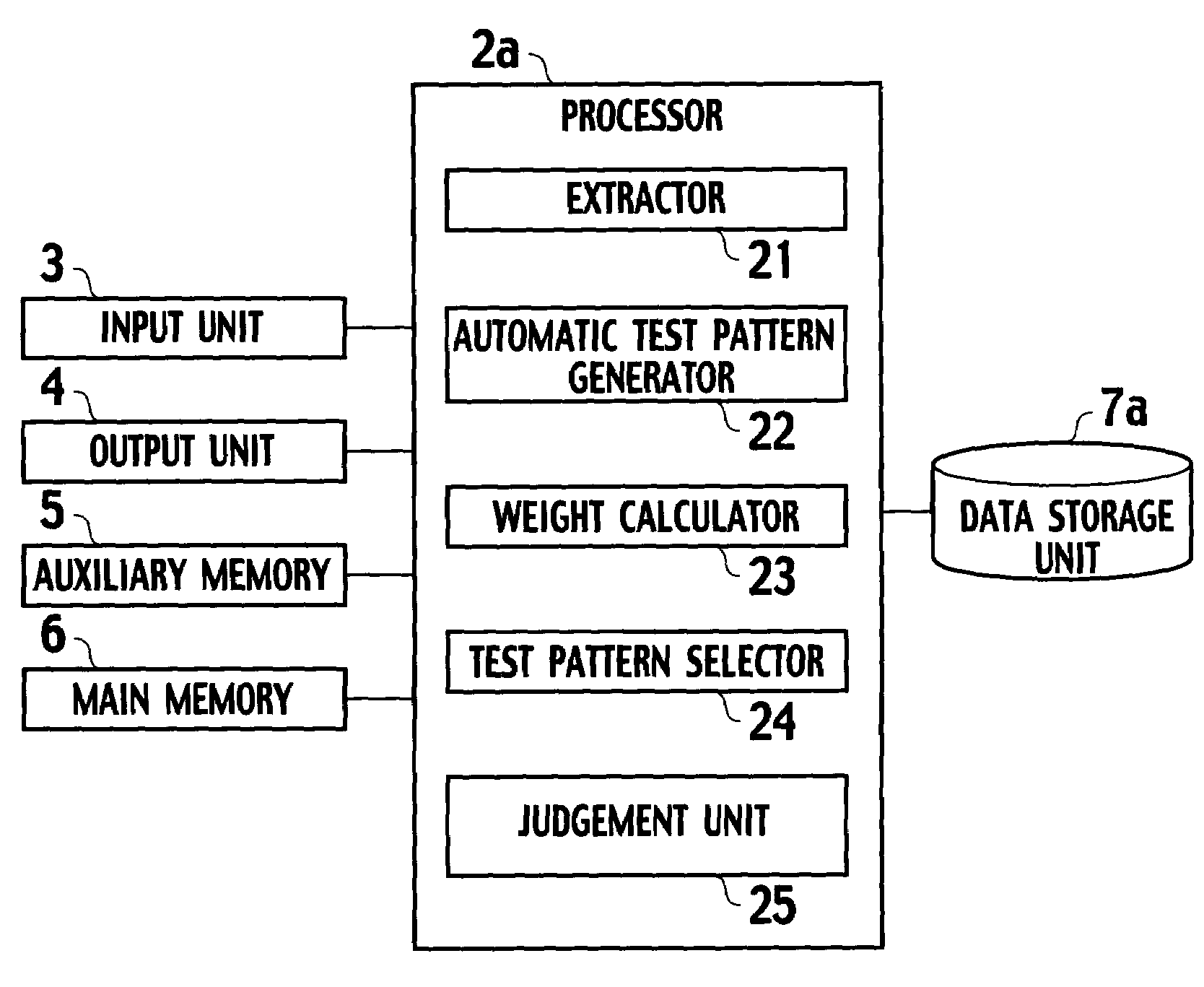
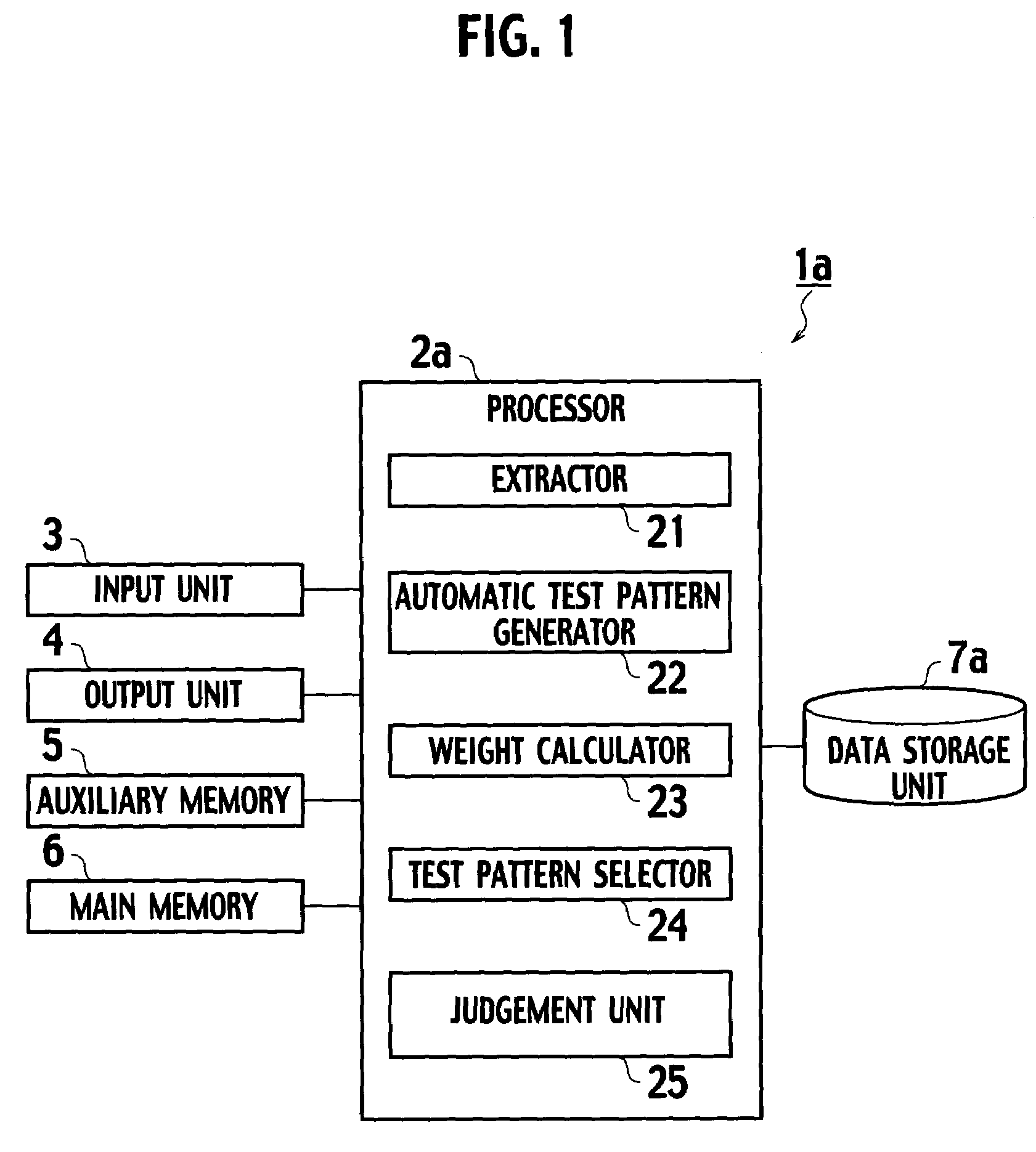
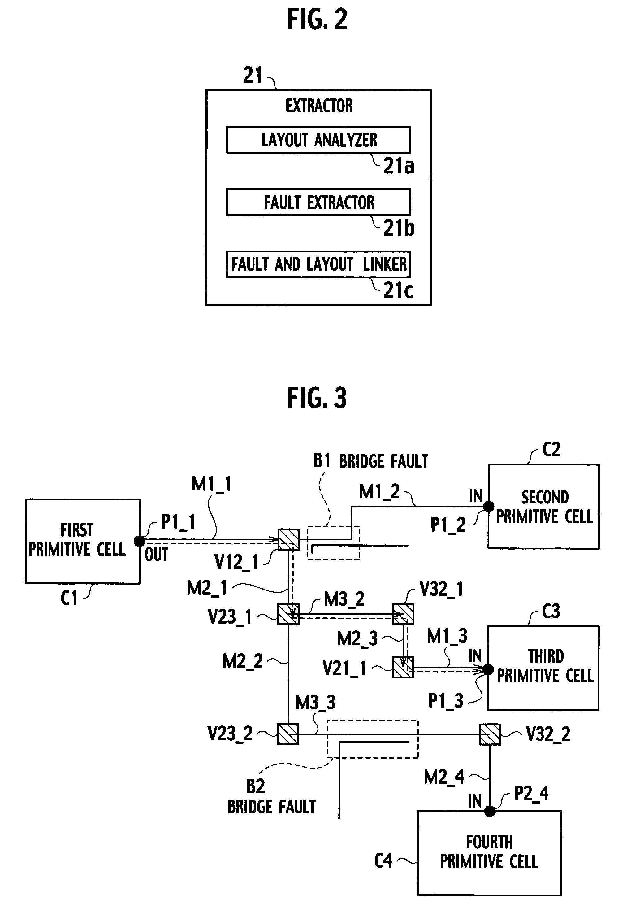
[0028]As shown in FIG. 1, a test pattern generating apparatus 1a, according to a first embodiment of the present invention, includes a processor 2a, an input unit 3 connected to the processor 2a, an output unit 4 connected to the processor 2a, an auxiliary memory 5 connected to the processor 2a, a main memory 6 connected to the processor 2a, and a data storage unit 7a connected to the processor 2a. The processor 2a includes an extractor 21, a test pattern generator 22, a weight calculator 23, a test pattern selector 24, and a judgment unit 25. The extractor 21 extracts a plurality of layout parameters (elements) of a circuit under test based on gate net information and layout information of the circuit, and links the layout parameters (elements) with corresponding fault models respectively. The weight calculator 23 calculates a weight for each fault model linked with the layout parameters (elements) for both a plurality of undetected faults of the fault model and a plurality of faul...

second embodiment

[0071]As shown in FIG. 8, a test pattern generating apparatus 1b according to second embodiment of the present invention is similar to the test pattern generating apparatus 1a shown in FIG. 1. As shown in FIG. 9, an analyzer 210 includes an acquisition unit 21d configured to acquire temporary test patterns from the data storage unit 7b. As shown in FIG. 10, the data storage unit 7b includes a temporary test pattern storage 94 configured to store temporary test patterns generated regardless of weights, and a fault list storage 95. Other arrangement is similar to test pattern generating apparatus 1a shown in FIG. 1.

[0072]A function test, a scan test, and a BIST can be utilized as a technique of obtaining the temporary test patterns. The test pattern generator 22 may generate temporary test patterns by generating test patterns at random to an appropriate level.

[0073]Next, a method for automatically generating test patterns will be described with reference to FIG. 8 to FIG. 11. Repeated...

third embodiment

[0088]As shown in FIG. 12, a test pattern generating apparatus 1c, according to a third embodiment of the present invention, further includes a processing state judgment unit 26 configured to judge whether a procedure of a final layout is completed. As shown in FIG. 13, the data storage unit 7c further includes a temporary layout information storage 96. The temporary layout information is obtained by an outline wire tool such as floor planner or usual place & route tool. Other arrangement is similar to test pattern generating apparatus 1a shown in FIG. 1.

[0089]Next, a method for automatically designing a circuit according to the third embodiment will be described with reference to FIG. 12 to FIG. 14. Repeated descriptions for the same processing according to the third embodiment which are the same as the first embodiment are omitted.

[0090]In step S101, an entire layout of the circuit under test is analyzed, based on the gate net information and temporary layout information stored in...


PUM


Abstract

A test pattern generating apparatus includes an extractor configured to extract a plurality of layout parameters (elements) of a circuit under test based on gate net information and layout information of the circuit, and to link the layout parameters (elements) with corresponding fault models respectively. A weight calculator is configured to calculate a weight for each fault model linked with the layout parameters (elements) for both a plurality of undetected faults of the fault model and a plurality of faults detected by a plurality of test patterns, based on process failure (defect) information and layout parameter (element) information. An automatic test pattern generator is configured to generate the test patterns in accordance with the weight of each fault model linked with the layout parameters (elements).

Description

CROSS REFERENCE TO RELATED APPLICATION AND INCORPORATION BY REFERENCE[0001]This application is based upon and claims the benefit of priority from the prior Japanese Patent Applications No. P2004-184177, filed on Jun. 22, 2004; the entire contents of which are incorporated herein by reference.BACKGROUND OF THE INVENTION[0002]1. Field of the Invention[0003]The present invention relates to a test technology of semiconductor integrated circuits, and more particularly, relates to a test pattern generating apparatus, a method for automatically generating test patterns, and a computer program product for executing an application for a test pattern generating apparatus capable of automatically generating the test patterns.[0004]2. Description of the Related Art[0005]Recently, a large-scale integrated circuit (LSI) called a system on chip (SOC) has been widely developed. The LSI is frequently manufactured by use of a deep sub-micrometer (DSM) process using metal wires having a width less tha...

Claims


Application Information

Patent Timeline
Patent Type & Authority Patents(United States)
IPC IPC(8): G01R31/28
CPCG01R31/31835
Inventor NOZUYAMA, YASUYUKI
Owner KK TOSHIBA
Learn More