
Weighted zero solids loss circulation, fluid loss and insulating annular space fluid systems

a circulation and fluid system technology, applied in the direction of insulation, sealing/packing, borehole/well accessories, etc., can solve the problems of slow or rapid loss of drilling mud, high cost of complex drilling mud, and high cost of drilling a well, so as to reduce the rate of dissolution of the composition of the present invention and achieve the effect of easy separation

Inactive Publication Date: 2008-08-05
CABOT SPECIALTY FLUIDS
View PDF13 Cites 9 Cited by
  • Summary
  • Abstract
  • Description
  • Claims
  • Application Information

AI Technical Summary

Benefits of technology

[0060]Generally, the compositions of the present invention can be introduced into the well by a coil tubing which fits inside the production tubing of a well. This coil tubing can be inserted such that it can reach any point of the well and preferably reaches to the bottom of the well where the compositions of the present invention can be pumped and / or jetted, also known as bullheading, into the well bore. The density of the compositions of the present invention should be such that the composition remains at the location where it was introduced, if desired. With the proper density, the oil or other hydrocarbons being recovered can displace the gel remnants after the acid has opened up productivity from the formation face. Over time, the rate of the dissolution of the compositions of the present invention will decrease by being contacted with the oil and any other water being released during recovery of the hydrocarbons. This will eventually dilute the compositions such that the composition is eventually pumped to the surface along with the recovery of hydrocarbons to the surface. Once recovered at the surface, the composition of the present invention will separate from the hydrocarbon, such as oil, by the separation of water / oil phases. Accordingly, the recovery of hydrocarbons is not affected by the use of the composition of the present invention, and is quite easily separated as well.
[0061]As an additional embodiment of the present invention, the present invention relates to a fluid loss spotting pill containing the loss circulation fluid of the present invention. In another embodiment of the present invention, the present invention involves a slug containing the loss circulation fluid of the present invention. As with the loss circulation fluid, the fluid loss spotting pill or slug in one or more embodiments requires no carrier fluid since, in preferred embodiments, there is substantially no or completely no solids present in the loss circulation fluid of the present invention. Furthermore, in the present invention, the loss circulation fluid and the manner of delivery involves a one part system. In other words, there is no two or multiple part systems required to activate the loss circulation fluid or to cause it to gel. In the present invention, as described above, the high temperatures in the well bore will thermally activate the gel causing the gelling of the gel forming material.
[0062]Thus, the spotting pill can be injected into the loss zone to form a substantially or completely impermeable filter cake to seal pores or fractures in the loss zone. As an option, once the filter cake is thoroughly set and loss has stopped, the filter cake can be later remediated by exposure to an acid solution (or base solution), as discussed above, which breaks the gel apart and allows a free-flowing reservoir for hydrocarbon production. The loss circulation fluid or spotting pill can be used in both producing and non-producing intervals of the well bore.
[0063]While preferred embodiments of the present invention involve zero solids in the loss circulation fluid, as an option, the loss circulation fluid can have a solid content of, for instance, up to 50 lbs per bbl, or preferably from about 10 lbs per bbl to about 35 lbs per bbl. The solids can have a particle size distribution that will optimally bridge the pores or fractures of the formation. One example of a suitable solid is calcium carbonate. Other conventional solids used in the drilling fluid industry can be used.

Problems solved by technology

The more complex drilling muds can be very costly and their loss can mean a substantial increase in the cost of drilling a well.
This loss of drilling mud may be slow or rapid depending upon the degree of porosity or the size of the fissures or fractures in the formation.
In more severe cases the loss of fluid may result in a drop in the hydrostatic head to the point of hydraulic pressure equalization, which may fall thousands of feet below the surface.
In this instance, several conditions may occur which endanger the drilling operation and result in considerable economic loss.
Therefore, when a well bore is partially or completely emptied of drilling mud, the well bore walls are deprived of the hydraulic pressure head of the column of drilling circulation fluid extending downward from the surface, and consequently there will be hundreds or even thousands of feet of unsupported well wall that will be free to slough off and to cave into the well bore.
That sloughing off or caving in may stick or freeze drill pipe that may be in the well bore or casing that may be therein and which is in the process of being installed and cemented.
When drilling mud is lost in a well bore, the formation penetrated may be under great pressure which, if sufficient to overcome the static head of drilling mud remaining in the well bore, will cause a blowout, endangering the well, the financial investment in it, and the lives and safety of the personnel on site.
Where casing is being installed and cemented in place or cement plugs are being installed or other cementing operations are taking place, Portland cement slurries are often employed and these slurries likewise become lost through porous or fractured formations penetrated by the well bore.
As oil and gas wells are being drilled to progressively greater depths in the earth the problem of preventing or curing lost circulation becomes increasingly difficult largely due to the high differential in pressures encountered in the formations penetrated by deep well bores.
Lost circulation of drilling fluids has been a problem since the earliest days of well drilling.
However, formations are frequently encountered that are so porous as to increase the loss of drilling fluids beyond an acceptable limit despite the use of lost circulation additives.
Furthermore, a borehole may penetrate a fracture in the formation through which most of the drilling fluid may be lost.
A disadvantage with many previous loss circulation fluids and drilling fluids is that they contain a large amount of solids (e.g., barite, hematite or ilmenite) from the various components present, such as the weighting materials or other materials used to plug the lost circulation zones, such as ground nut shells, ground fibrous materials or ground plastics such as polyethylene.

Method used


Image

  • Weighted zero solids loss circulation, fluid loss and insulating annular space fluid systems

Examples


example 1

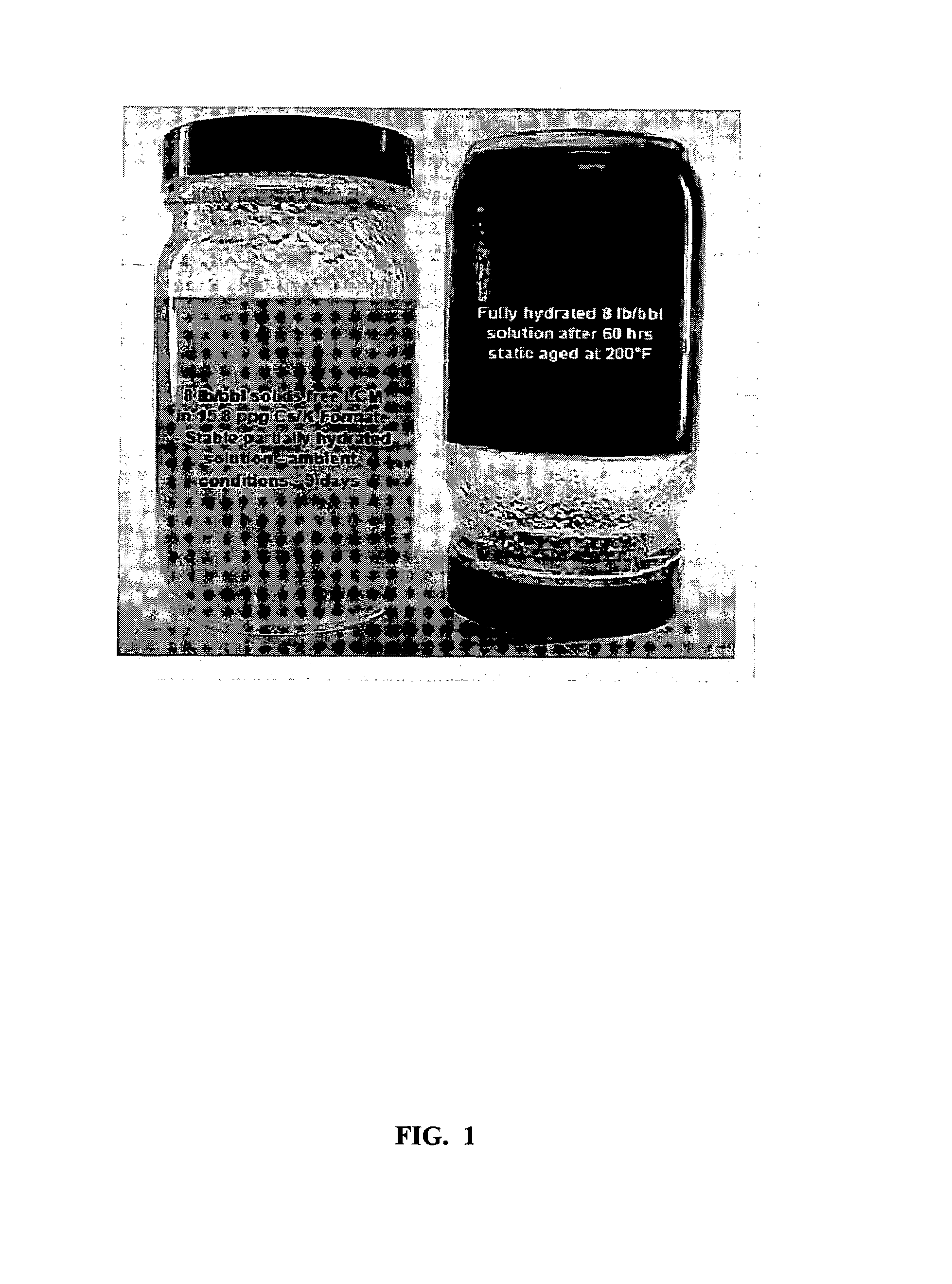
[0067]In the following example, a loss circulation fluid was prepared by taking a 15.8 lb. per barrel of a blend of cesium formate and potassium formate buffered pH of 10.02. In particular, the cesium formate was present in an amount of 48 wt % of a 2.2. s.g. cesium formate solution and the potassium formate was present in an amount of 52 wt % of a 1.57 s.g. potassium formate. In this example, 2 lbs. per barrel, or 5 lbs. per barrel, or 8 lbs. per barrel of carboxymethyl guar was present in the loss circulation fluid. The material was subjected to a standard Fann 35 viscometer test to determine the rheological properties of the three fluids which involved subjecting the three loss circulation fluids to a rotating blank having standard readings taken at 600, 300, 200, 100, 6 and 3 rpm or a range of various settings to achieve a desired rpm as shown in the table below.

[0068]The table below represents the typical initial properties of an oilfield fluid system which is run on a Fann 35 ...

example 2

[0071]A Fann 70 rheological profile on a sample of the fluid in Example 1 was conducted. The fluid was the buffered 15.8 ppg Cs / K Formate with 8.0 lbs / bbl LCM. The fluid was heated from 75° F. to 375° F. in 25° F. increments. At each temperature, the Fann 70 reading at 60 rpm and 6 rpm was taken. A second Fann 70 test was run to measure the increase in viscosity of the fluid while maintaining a constant temperature of 200° F. and pressure of 400 psi. This test was run for 19 hours.

[0072]The purpose of the first Fann 70 test was to determine at what temperature the fluid began to show an increase in viscosity. The test was continued to determine the maximum temperature that the fluid would withstand. The purpose of the second test was to determine if viscosity would increase with time while holding a constant temperature and pressure on the fluid.

First Fann 70 Test

[0073]The fluid showed a rise in 60 rpm and 6 rpm values between 150° F. and 175° F. The fluid continued to gain viscosit...


PUM

PropertyMeasurementUnit
temperatureaaaaaaaaaa
pHaaaaaaaaaa

Abstract

Loss circulation fluids contain aqueous based compositions having at least one alkali metal formate and at least one thermally activated self-crosslinkable gel forming material, wherein the composition is easily transported to a loss circulation zone and yet has ability to close off the loss circulation zone once thermally activated to reduce the loss of circulation fluids into flow passages of a subterranean formation. In addition, packer fluids contain aqueous based compositions which contain at least one alkali metal formate and at least one thermally activated self-crosslinkable gel forming material, wherein the packer fluid forms a thermal insulating fully hydrated gel once thermally activated.

Description

BACKGROUND OF THE INVENTION[0001]The present invention relates to weighted zero solids loss circulation and / or fluid loss systems, such as for the drilling industry, like oil field drilling and completion operations.[0002]In one or more embodiments, the present invention relates to loss circulation fluids or loss circulation drilling fluids, and methods to control loss circulation fluids.[0003]In the drilling of well bores with modern rotary well drilling apparatus and methods, the bore hole is normally kept filled with clean circulating drilling mud, or other drilling fluid, which washes and flushes the cuttings removed by the rotary bit from the bottom of the well bore. Drilling muds, or other drilling fluids, are pumped under pressure down the interior of the drill pipe and are forced out through openings in the drill bit, providing lubrication and wetting of the exposed surface, which increases the efficiency of the bit. The fluid then lifts the rock cuttings produced by the bit...

Claims


Application Information

Patent Timeline
Patent Type & Authority Patents(United States)
IPC IPC(8): C09K8/506C09K8/508C09K8/512
CPCC09K8/506C09K8/512C09K8/508
Inventor BENTON, WILLIAM J.
Owner CABOT SPECIALTY FLUIDS
Learn More