
Branched flow filtration and system

a filtration system and branch flow technology, applied in the direction of membranes, filtration separation, separation processes, etc., can solve the problems of reducing the overall number of required pipe connections, requiring extensive pretreatment equipment, and high pressure piping and valves required for feeding pressure vessels are relatively more expensive. , to achieve the effect of improving operation and/or performan

Inactive Publication Date: 2008-08-12
IONICS INC
View PDF13 Cites 54 Cited by
  • Summary
  • Abstract
  • Description
  • Claims
  • Application Information

AI Technical Summary

Benefits of technology

"The present invention is a system that uses a pressure vessel with a side entry port to produce two separate streams of permeate. The system can use a single vessel with multiple filter cartridges or separate vessels for different stages of treatment. The system can also control the pressure and back pressure on individual filter elements to enhance operation and performance. The system can be used in high capacity water purification plants with multiple banks of vessels in series. The system has higher flux and lower pressure drop compared to conventional systems, and can operate with lower power costs. The system can also be designed with little or no additional valving or special plumbing."

Problems solved by technology

High pressure piping and valves required for feeding pressure vessels are relatively more expensive than the lower-pressure conduits employed for the permeate and reject streams, and provision of multi-element pressure vessels reduces the overall number of required pipe connections.
All of these processes require extensive pretreatment equipment, and most also involve substantial chemical usage on an ongoing basis.
While the use of modular arrays of multi-element vessels allows one to scale plant size relatively easily and to connect with upstream and downstream processes, it does not provide much flexibility of the filtration stage itself.
However, applicant is not aware of commercial systems of the type indicated in that patent.
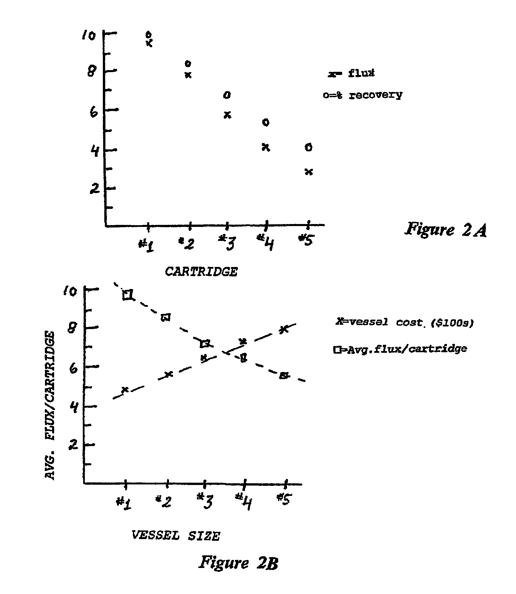
In the modern systems employing long, multi-cartridge pressure vessels, there is a practical limit to the number of filtration elements that can be effectively utilized in this manner within a single pressure vessel.
This limit is a consequence of the trade-off inherent in the cross flow filtration process.
Each of these factors lowers the productivity or efficiency of the downstream modules and the quality of the downstream permeate.
In constructing multi-cartridge pressure vessels, the end caps or manifolds with their pipe fittings are appreciably more expensive than the plain cylindrical-walled portions of the pressure vessel.
Thus, the cylindrical body of a glass composite pressure vessel rated at 1000 psi may be manufactured for about $20-40 per linear foot (thus, $40-$120 per cartridge), while an end cap with inlet, suitable sealing faces, and permeate and possibly brine outlet connections may cost several hundred dollars, substantially raising the price of the vessel.
However, as discussed above, while the relatively low marginal cost of adding additional filter modules in a linear section of pressure vessel is inviting, a reduction in relative yield and quality occurs with the addition of further filtration elements in the vessel.
Cartridges may scale or foul.
These factors may therefore combine to drive down performance or increase capital costs, operating costs or both in a way that ultimately requires steady-state operation at less than optimum efficiency or at less than the intended or the rated capacity.
These systems may involve large operating costs for energy and chemicals in addition to the initial capital expenses of construction and plumbing, and they require periodic membrane or cartridge replacement.
The use of conventional, multiple element pressure vessels may in some circumstances lower the capital cost of such systems by providing greater capacity without additional construction costs; however, the compromise of operating efficiency as noted above attendant with the use of such vessels may increase the later operating costs for the same systems.
Institutional predispositions or weaknesses within a contracting authority, such as a public water board, as well as the bidding process itself may bias the evaluation of treatment plant designs and result in a failure to fully consider or understand future performance or maintenance cost issues.
Nonetheless, current modular filtration systems have become increasingly locked into the use of basic units having these limitations.

Method used


Image

  • Branched flow filtration and system
  • Branched flow filtration and system
  • Branched flow filtration and system

Examples


Embodiment Construction

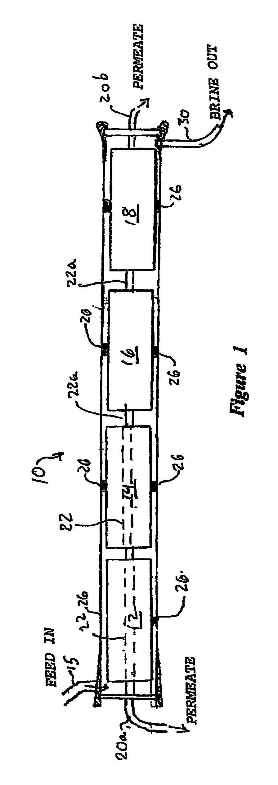
[0049]FIG. 1 illustrates the context of the invention, showing by way of example a typical conventional pressure vessel 10 of the prior art that holds a plurality of reverse osmosis or filtration membrane modules or cartridges 12, 14, 16, and 18. For clarity of illustration, only a few cartridges are shown, although as noted above, a vessel of this type may in practice be sized to hold six to eight or more RO membrane modules. The illustrated vessel 10 has an inlet 15 for feed fluid at its proximal end, outlets 20a, 20b for permeate that has passed through the filtration modules 12, 14, 16, and 18, and a reject or retentate outlet 30 at the distal end for the remaining (unfiltered) liquid residue from the feed stream. The feed is applied at one end to the interior space of the vessel, and the permeate is collected via conduit 22 located on the central axis of the vessel that serves as a collection manifold. The conduit 22 is typically comprised of conduit segments that are each asso...


PUM

PropertyMeasurementUnit
pressureaaaaaaaaaa
diameteraaaaaaaaaa
pressureaaaaaaaaaa

Abstract

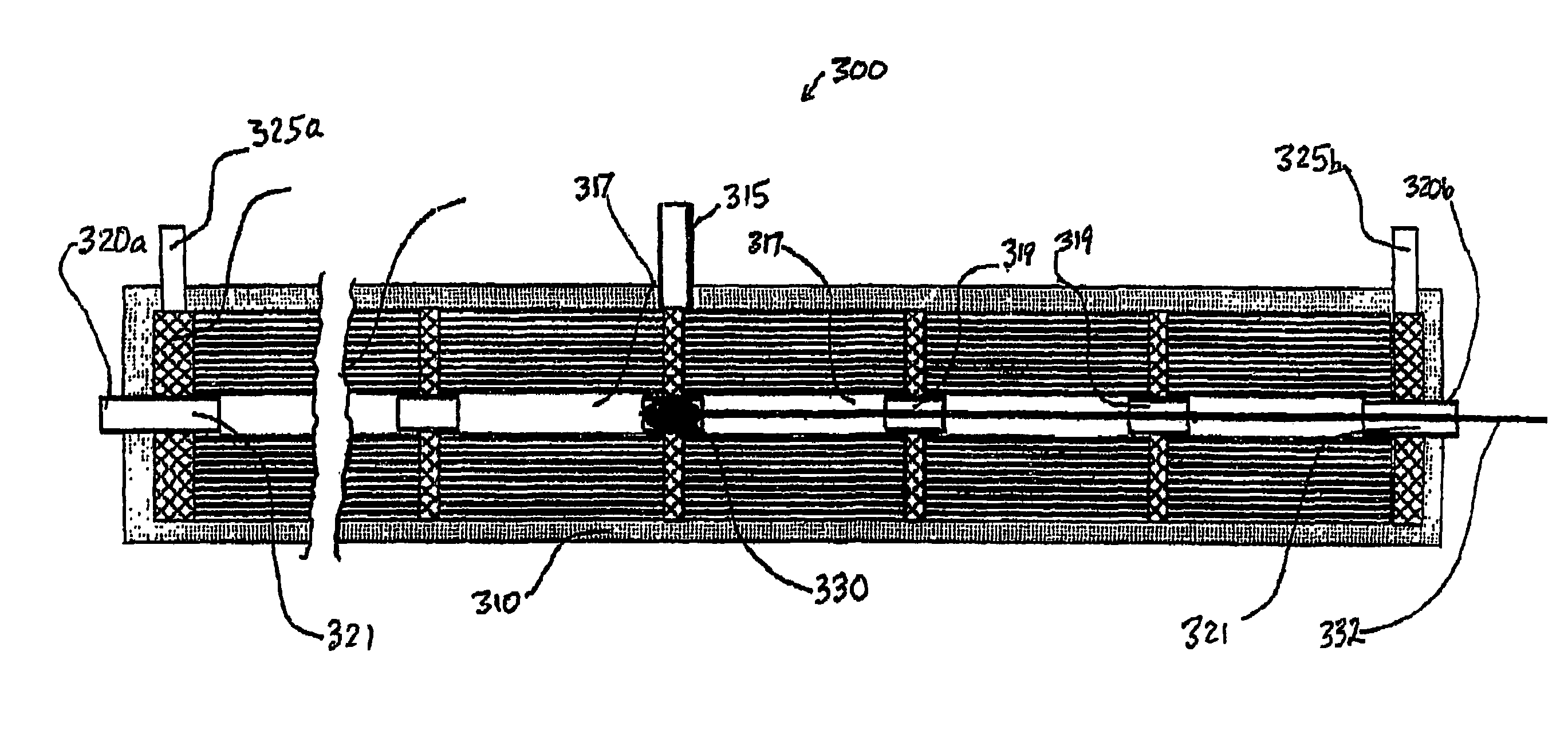
A cross flow filtration apparatus for nanofiltration or reverse osmosis has pressure vessels with a plurality of filter cartridges in each vessel. A feed port is provided at an intermediate position on the side of the vessel, and two permeate flows or branches exit opposite ends of the vessel, and the first branch has a characteristically high “upstream” flux and quality, while the second is of lesser flux and / or quality. The system provides a high degree of moduarity, enhancing flux or yield at a reduced driving pressure or overall pressure drop. Centered or off-center port, and a stop or valve in the permeate stream may apportion flows between the two outlets. Staged systems may employ a first stage bypass to achieve a target quality with increased yield. A flow divider or adaptor permits the cartridges to fit and seal in the vessel and an installation tool or sleeve may facilitate installation or replacement of cartridges having a directional perimeter seal. A tool permits modules to be bi-directional installed in the pressure vessel. Other embodiments involve adapting a conventional vessel designed for end-to-end feed flow utilizing a restrictor, obstruction or valve inside the filter cartridge to bifurcate or otherwise split or apportion the permeate. RO elements may be modified to movably position an obstruction or valve along a string of the elements and vary the take-off to two or more permeate outlets, or to provide pressure relief valves that present different pressure conditions for different elements of a string. A pressure vessel may have an intermediate inlet, with symmetric or asymmetric branching of permeate flow to opposed ends of the vessel, enhancing permeate flux, permeate quality and / or energy efficiency.

Description

CROSS REFERENCE TO RELATED APPLICATIONS[0001]This application claims priority to international application PCT / US02 / 35352, filed Nov. 5, 2002, which in turn claims the benefit of U.S. Application Ser. Nos. 60 / 332,878 filed Nov. 6, 2001 and 60 / 392,225 filed Jun. 28, 2002.[0002]This invention pertains to filter elements and vessels, and systems and methods for filtration of fluids, such as water, to achieve a fluid product of a specified quality level. It particularly relates to high flow or cross flow filtration apparatus, such as nanofiltration (NF) or reverse osmosis (RO) wherein the filter modules are typically arranged in a string or series in the feed flow, and wherein the filtrate quality with respect to at least one removable material constituent in the feed stream, and / or wherein the filtrate quantity, varies progressively with position along the path. The filtration apparatus of the invention employs novel filtration elements and / or pressure vessels wherein the filtration el...

Claims


Application Information

Patent Timeline
Patent Type & Authority Patents(United States)
IPC IPC(8): B01D63/12B01D63/06B01D63/10B01D61/00B01D63/04B01D61/02B01D61/10B01D61/12B01D63/00B01D65/00C02F1/44
CPCB01D61/02B01D61/022B01D61/025B01D61/027B01D61/10B01D61/12B01D63/10B01D63/106B01D63/12B01D65/00C02F1/441B01D63/043C02F1/442B01D2313/18B01D63/107B01D61/029B01D63/04
Inventor ARNOLD, JOHN W.ELYANOW, IRVING D.CARSON, WILLIAM W.
Owner IONICS INC
Learn More