Sample handling plate

a sample handling and plate technology, applied in the field can solve the problems of deteriorating measurement accuracy, affecting the accuracy of measurement, and causing plate warpage as that of plastic plates, so as to suppress the warpage of sample handling plates, suppress the warpage of plates, and reduce the shrinkage coefficien

Inactive Publication Date: 2008-08-12
ENPLAS CORP
View PDF14 Cites 29 Cited by
  • Summary
  • Abstract
  • Description
  • Claims
  • Application Information

AI Technical Summary

Benefits of technology

[0014]It is therefore an object of the present invention to eliminate the aforementioned problems and to provide a sample handling plate capable of being prevented from warping when being produced and capable of being used for carrying out a precise measurement by means of an optical measuring unit having a narrow focal point.
[0023]In an embodiment of the present invention, the warpage of a sample handling plate is suppressed by a reinforcing rib formed on the side of the reverse of the plate, or by a member, such as a metal body, which is formed on the side of the reverse of the plate so as to be integrated therewith, the member being made of a material having a lower coefficient of shrinkage than that of plastics.
[0024]According to the present invention, the same measures as those taken for a sample handling plate of a plastic may be taken for a plate of a material, such as a glass, other than plastics to suppress the warpage of the plate.
[0025]According to the present invention, the amount of shrinkage on the side of the surface of the sample handling plate can be substantially equal to that on the side of the reverse thereof after the injection molding, so that it is possible to suppress the warpage of the sample handling plate. It is also possible to suppress the warpage of the sample handling plate by the reinforcing rib formed on the side of the reverse of the sample handling plate, or by the metal body formed on the side of the reverse of the sample handling plate so as to be integrated therewith. Thus, measuring light emitted from an optical measuring unit can be easily focused on a sample held on or housed in the sample handling plate.

Problems solved by technology

When the plate 100, 102 or 106 thus warps, if a sample is measured by an optical measuring unit having a narrow focal point using laser beams or the like, the position of the focal point is displaced, so that there is the possibility that the precision of measurement deteriorates.
Furthermore, if a plate of a material, such as a glass, other than plastics is used as a sample handling plate, the same warpage of the plate as that of a plastic plate may be caused.

Method used


Image

  • Sample handling plate
  • Sample handling plate
  • Sample handling plate

Examples


example 1

[0077]FIGS. 16 and 17 show a sample handling plate 31 in Example 1 according to the present invention. As shown in these figures, the sample handling plate 31 in this example comprises a thin plate portion 32, and a frame portion 33 surrounding the periphery of the plate portion 32. The plate portion 32 is connected to the frame portion 33 so as to be arranged in a substantially central portion of the frame portion 33 in thickness directions. The surface 32a of the plate portion 32 has a large number of minute protrusions 35, each of which has a top face 34 to which a sample (DNA fragment or the like) to be analyzed is allowed to adhere. The reverse 32b of the plate portion 32 has a large number of minute protrusions 36 which have the same shape as that of the protrusions 35 on the side of the surface 32a of the plate portion 32 and which are arranged so as to correspond to the protrusions 35. Thus, the shape of the sample handling plate 31 is symmetrical with respect to the central...

example 2

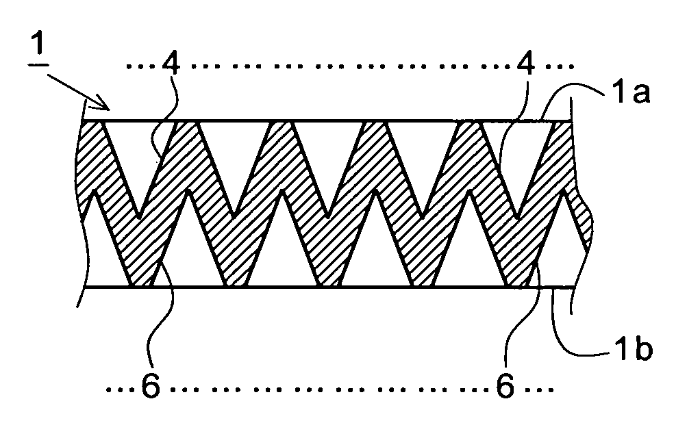
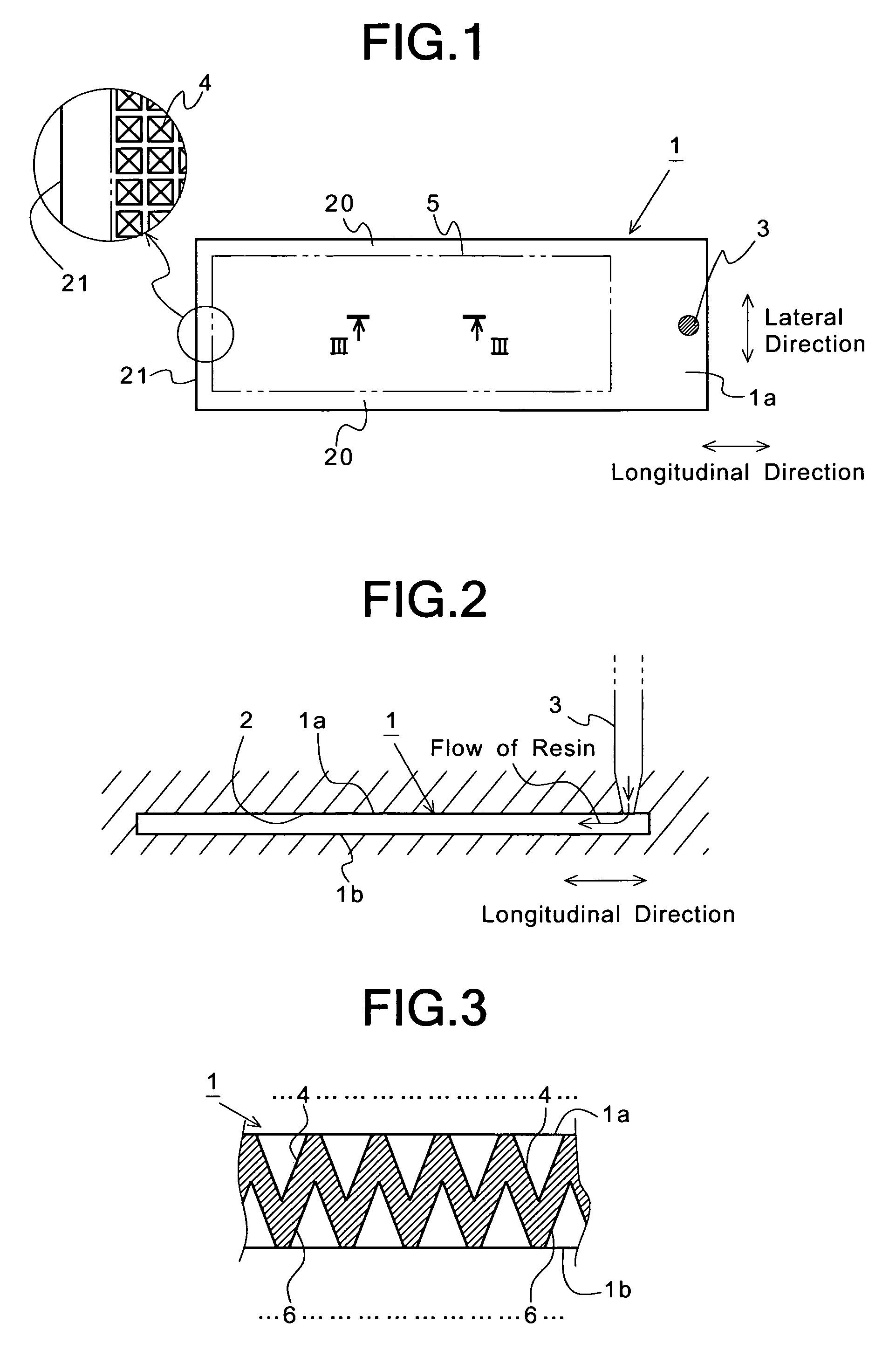
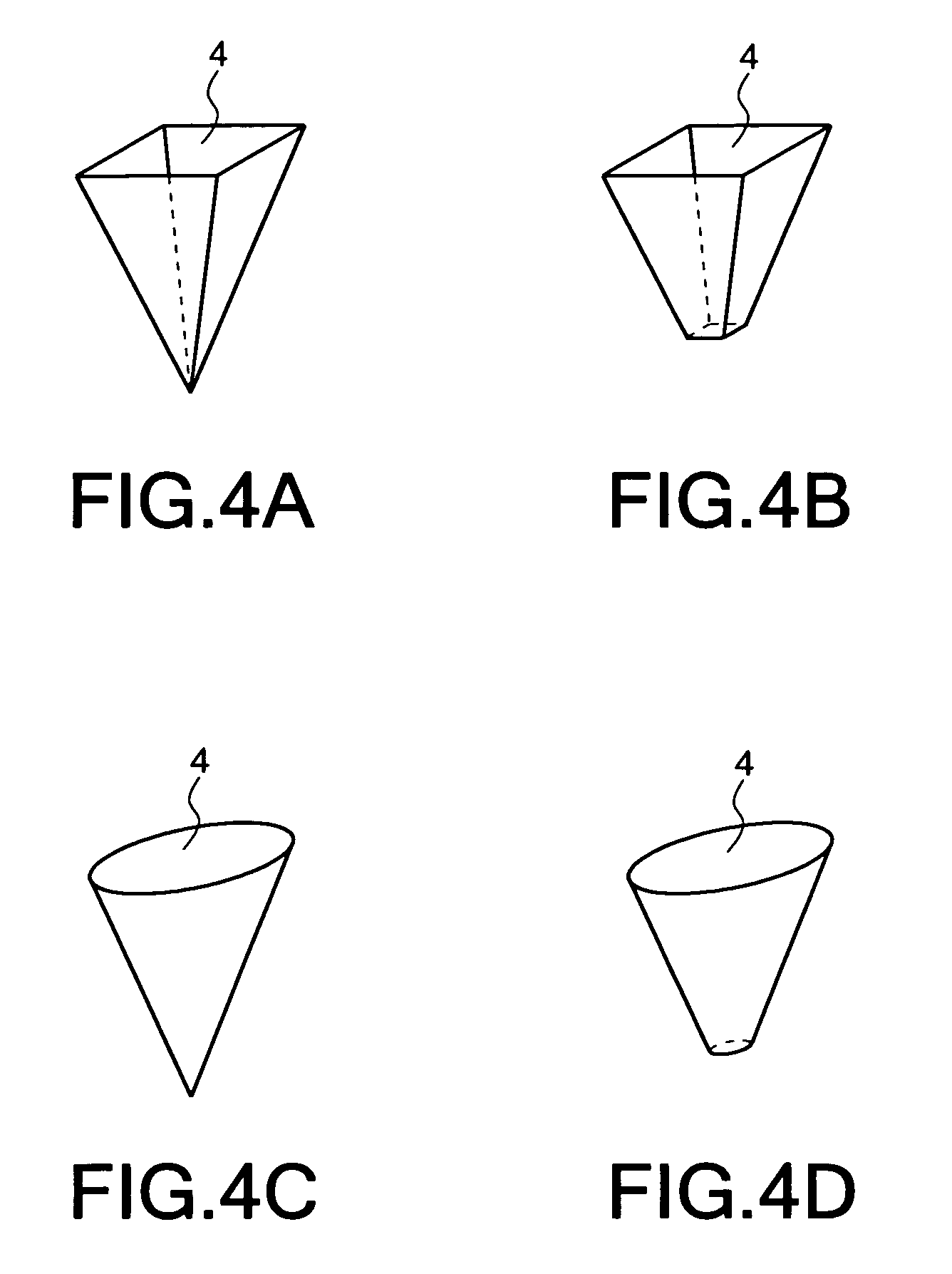
[0078]FIGS. 18 and 19 show a sample handling plate 41 in Example 2 according to the present invention. As shown in these figures, the sample handling plate 41 in this example has minute wells (recessed portions) 42 on the side of the surface 41a thereof, and recessed portions (lightening portions) 43 on the side of the reverse 41b thereof. The recessed portions 43 have the same shape as that of the wells 42. The wells 42 and the recessed portions 43 are symmetrical with respect to a central plane 44 in thickness directions of the sample handling plate 41. Thus, the amount of shrinkage on the side of the surface 41a is equal to that on the side of the reverse 41b during cooling after the injection molding, so that it is possible to suppress the warpage of the sample handling plate 41.

example 3

[0079]FIGS. 20 and 21 show a sample handling plate 51 in Example 3 according to the present invention. As shown in these figures, the sample handling plate 51 in this example has a lattice-shaped reinforcing rib 52 on the side of the reverse 51b thereof. When the sample handling plate 51 is used in a heating environment for causing a temperature difference between the surface and reverse thereof, the reinforcing rib 52 prevents the warpage of the sample handling plate 51 due to the temperature difference between the surface and reverse thereof. Thus, since the warpage of the sample handling plate 51 is prevented even if the sample handling plate 51 in this example is used in a heating environment for causing a temperature difference between the surface and reverse thereof, it is possible to precisely focus irradiation light beams on a sample in each of a large number of minute wells (recessed portions) 53 formed on the side of the surface 51a of the sample handling plate 51, so that...


PUM

PropertyMeasurementUnit
thicknessaaaaaaaaaa
lengthaaaaaaaaaa
lengthaaaaaaaaaa

Abstract

A sample handling plate 1 has wells 4 on the side of the surface 1a thereof, and lightening portions 6 on the side of the reverse 1b thereof, each of the wells 4 substantially having the same shape and volume as those of each of the lightening portions 6 so that the amount of shrinkage on the side of the surface 1a is equal to that on the side of the reverse 1b during cooling after the injection molding.

Description

BACKGROUND OF THE INVENTION[0001]1. Field of the Invention[0002]The present invention relates generally to a sample handling plate used for analyzing very small amounts of various samples (e.g., micro vital substances such as viruses and bacteria, vital formations such as cells and biopolymers, organic compounds other than biopolymers, inorganic substances and inorganic compounds). More specifically, the invention relates to a sample handling plate of a plastic, glass or the like, which is capable of being used for simultaneously examining the functions of a large number of genes and which is also capable of being used as a reactor in the PCR method for amplifying DNAs.[0003]2. Description of the Prior Art[0004]In recent years, of various methods for examining the functions of genes, the micro array technique capable of simultaneously examining thousands kinds to tens of thousands kinds of genes has been particularly noticed in the field of genome medical science and biochemistry.[0...

Claims


Application Information

Patent Timeline
Patent Type & Authority Patents(United States)
IPC IPC(8): B01L3/00G01N21/64B29C45/00G01N21/03G01N21/78G01N33/48G01N37/00
CPCB01L3/5085G01N21/0303B29C45/0025B01L2200/12B29C2045/0043B01L2300/0819
Inventor SAKAMOTO, YASUYUKI
Owner ENPLAS CORP
Why Eureka
Try Eureka