Vector controller of induction motor

a vector control and induction motor technology, applied in the direction of electric generator control, dynamo-electric converter control, dynamo-electric gear control, etc., can solve the problems of unstable rotation velocity and inability to fit velocity sensors to electric motors, so as to reduce unstable areas and avoid unstable areas

Inactive Publication Date: 2008-08-12
MITSUBISHI ELECTRIC CORP
View PDF14 Cites 19 Cited by
  • Summary
  • Abstract
  • Description
  • Claims
  • Application Information

AI Technical Summary

Benefits of technology

[0013]According to the vector control apparatus for an induction motor of the present invention, a magnetic flux command value is calculated back on the basis of a torque command value that is calculated by the torque command value arithmetic section on the basis of an input signal from the external system, a circuit constant of the induction motor, and an actual measurement related to the induction motor, and the SN ratio of the output voltage is increased, thereby making it possible to remarkably reduce the unstable area at the time of the low-speed operation even if the rotation velocity detecting means such as the velocity sensor is not particularly used.
[0014]Also, the magnetic flux command value is automatically calculated back so that the SN ratio of the output voltage can be set high at the time of the low-speed operation even when the induction motor is changed, thereby making it possible to avoid the unstable area. Thus, the present invention can be applied without conducting control adjustment.

Problems solved by technology

Also, in the case where the electric motor uses both ends of a shaft, or in the case where the installation location of the electric motor is limited, the velocity sensor cannot be fitted to the electric motor.
However, at the time of low-speed operation, because the output voltage value is very small, an error occurs in the output angular frequency, and there exists an area where the rotation velocity is unstable.

Method used


Image

  • Vector controller of induction motor
  • Vector controller of induction motor
  • Vector controller of induction motor

Examples


first embodiment

[0023]Hereinafter, a description will be given of the respective embodiments of the present invention with reference to the accompanying drawings. The identical or corresponding parts in the respective drawings are denoted by the same reference symbols, and will be described.

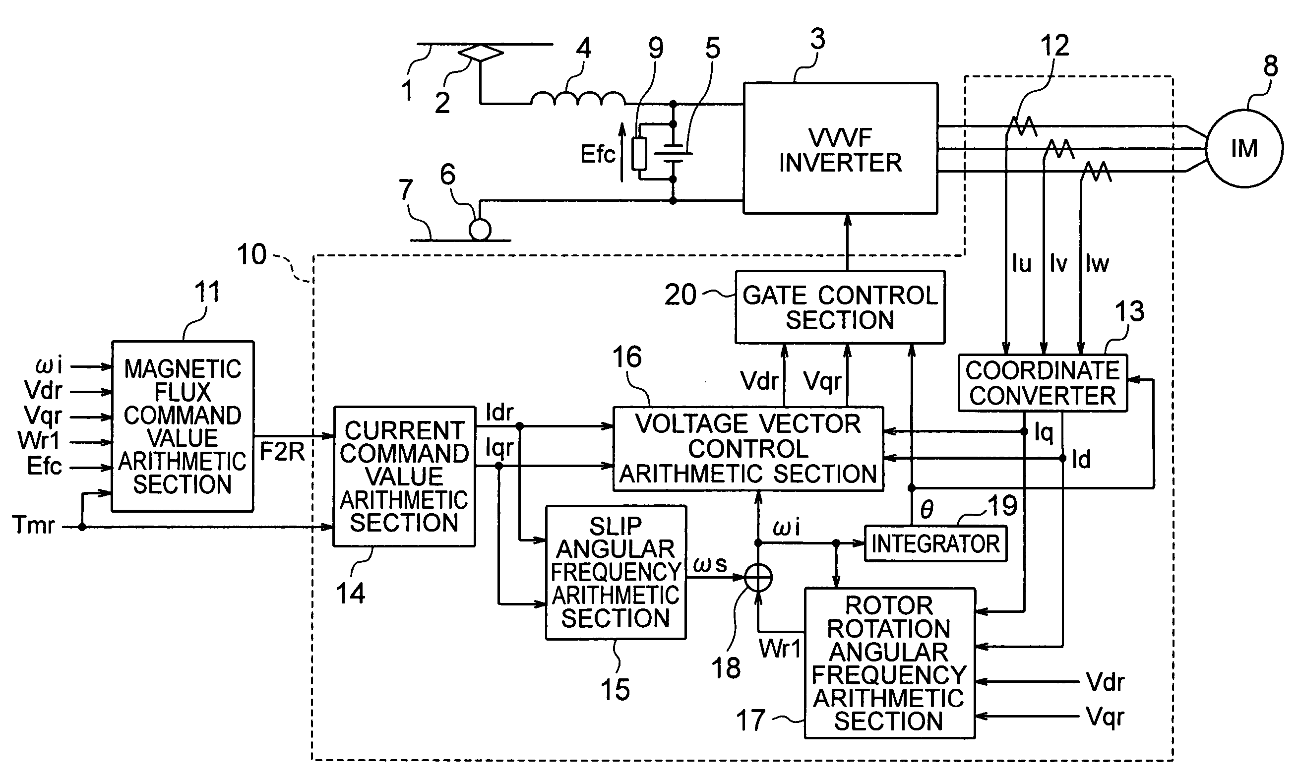
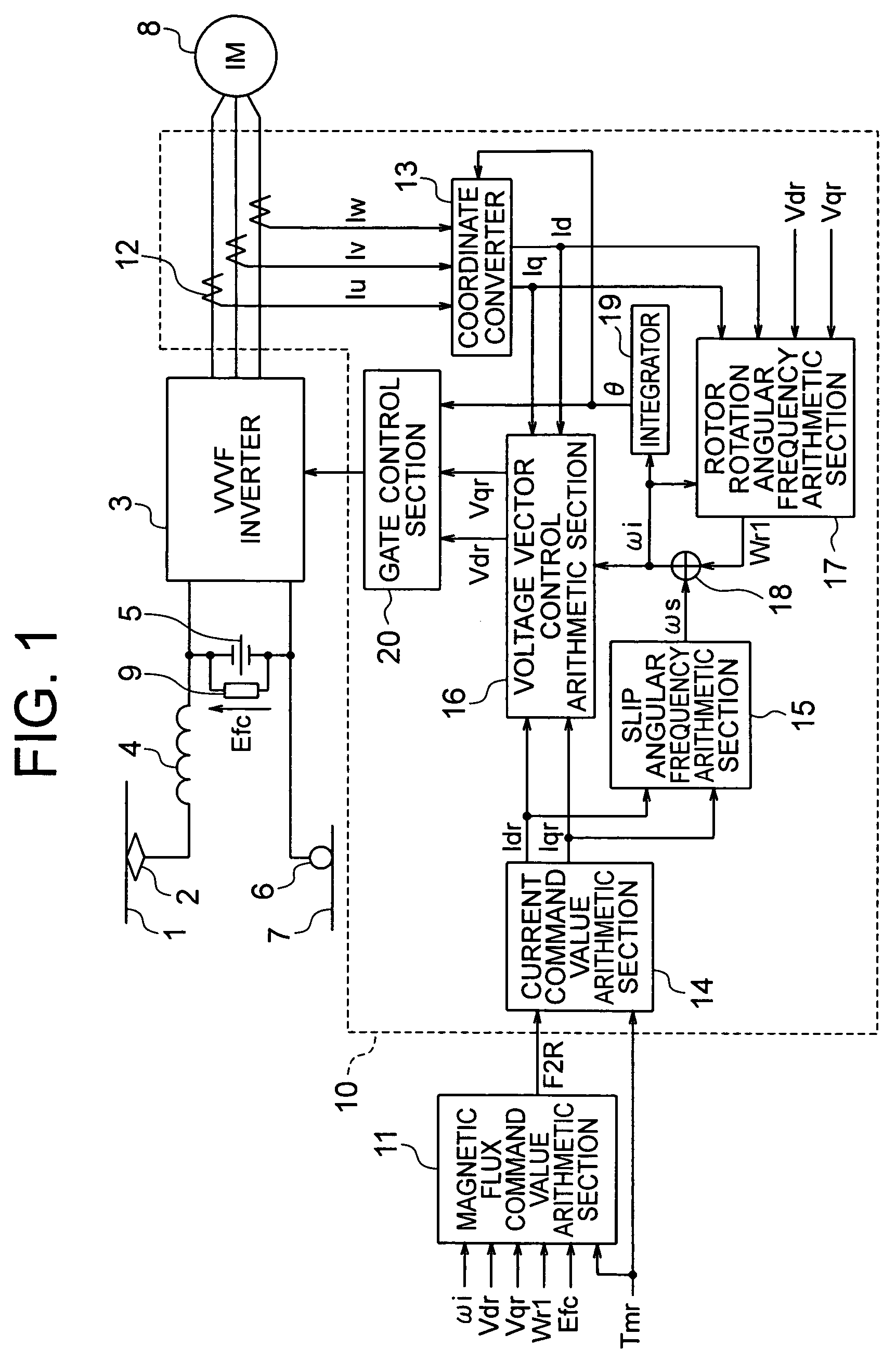
[0024]FIG. 1 is a block diagram showing a device configuration including a vector control apparatus for an induction motor according to a first embodiment of the present invention.

[0025]In the first embodiment, a DC electric vehicle will be exemplified, but the present invention can be applied to an AC electric vehicle, likewise.

[0026]Referring to FIG. 1, a main circuit of an electric vehicle includes an overhead wire 1 that supplies a DC power to an electric vehicle, a pantograph 2 that collects the DC power from the overhead wire 1, a VVVF inverter 3 that converts the DC power that has been collected from the overhead wire 1 into an AC power of an arbitrary frequency, a DC reactor 4 and a filter capacitor 5 th...

second embodiment

[0086]In the above first embodiment, in the magnetic flux command value arithmetic means, the magnetic flux command is changed over taking only the rotor rotation angular frequency into consideration. Further, the brake command can be taken into consideration.

[0087]The second embodiment is made by adding means for switching the magnetic flux command value according to the brake command to the first embodiment.

[0088]FIG. 6 is a block diagram showing a device configuration including a vector control apparatus for an induction motor according to a second embodiment of the present invention.

[0089]Referring to FIG. 6, a brake command B is input to a magnetic flux command value arithmetic means 11 in the vector control apparatus. Other configurations are identical with those in the first embodiment, and their description will be omitted.

[0090]FIG. 7 is a block diagram showing the magnetic flux command value arithmetic means 11 in the vector control apparatus for an induction motor shown i...


PUM


Abstract

Provided is a vector control apparatus for an induction motor which is capable of obtaining stable rotation in a short period of time for adjustment even at the time of low-speed operation by increasing the SN ratio of an output voltage to suppress the arithmetic error in the primary angular frequency arithmetic value based on a magnetic flux command value calculated from a circuit constant and an actual measurement of the induction motor even in the case where the rotation velocity of the induction motor is lower. The vector control apparatus includes a magnetic flux command value arithmetic section for selecting and outputting the magnetic flux command value on the basis of a torque command value that is externally input, the circuit constant of the induction motor, and the actual measurement related to the induction motor; and a vector controller for controlling an inverter device on the basis of the magnetic flux command value that is output from the magnetic flux command value arithmetic section and the circuit constant of the induction motor. The magnetic flux command value arithmetic section includes a magnetic flux command value back calculation arithmetic section for calculating a magnetic flux command arithmetic value so that a voltage that is applied to the induction motor becomes equal to or higher than a setting value corresponding to an unstable area.

Description

TECHNICAL FIELD[0001]The present invention relates to a velocity sensorless vector control apparatus for an induction motor, which is capable of remarkably reducing an unstable area at the time of low-speed operation even if rotation velocity detecting means such as a velocity sensor is not particularly used.BACKGROUND ART[0002]Vector control is performed by dividing a current of an AC electric motor into a magnetic field (i.e., magnetic flux) direction and a torque direction that is orthogonal to the magnetic field, thereby making it possible to control a magnetic flux current and a torque current, independently, and also to control a developed torque instantaneously as with a DC electric motor.[0003]The vector control requires a velocity sensor in order to measure the magnetic flux. However, an electronic circuit is normally incorporated into the velocity sensor, and an operating temperature range of the electronic circuit is narrower than the operating temperature range of the AC...

Claims


Application Information

Patent Timeline
Patent Type & Authority Patents(United States)
IPC IPC(8): H02P21/08H02P21/00H02P21/04H02P21/14H02P21/18H02P21/22H02P21/24H02P23/03H02P23/07H02P23/12H02P23/14H02P27/04
CPCH02P21/12H02P21/00
Inventor KONO, MASAKI
Owner MITSUBISHI ELECTRIC CORP
Why Eureka
Try Eureka