Reconfigurable magnetic logic device and preparation method therefor

A logic device and device technology, applied in the field of reconfigurable magnetic logic devices and their preparation, can solve the problems of difficult to guarantee device reliability, difficult to improve logic output, difficult to miniaturize devices, etc., and achieve outstanding performance and low operating magnetic field. , the effect of reducing energy consumption

Active Publication Date: 2017-02-01
TSINGHUA UNIV
View PDF3 Cites 7 Cited by
  • Summary
  • Abstract
  • Description
  • Claims
  • Application Information

AI Technical Summary

Problems solved by technology

For spin logic devices, the logic input is stored in the form of magnetization, and the logic operation between magnetic units is carried out through spin-related transport. It is always difficult to improve the logic output at room temperature, which makes it difficult to guarantee the reliability of this device.
For magnetic field logic devices, the nonlinear transport effect in semiconductors provides an ideal logic output ratio, but requires a large magnetic field, which makes it difficult to miniaturize such devices

Method used


Image

  • Reconfigurable magnetic logic device and preparation method therefor
  • Reconfigurable magnetic logic device and preparation method therefor
  • Reconfigurable magnetic logic device and preparation method therefor

Examples


Embodiment 1

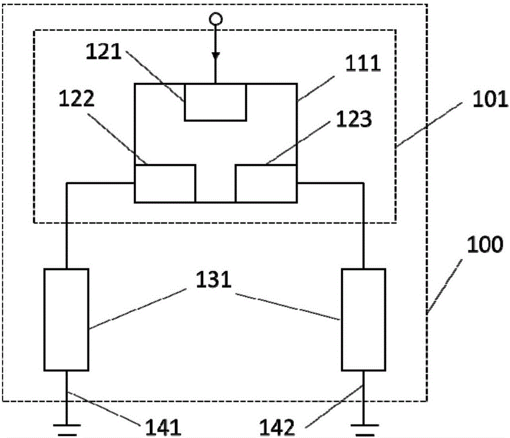
[0025] For the magnetic unit 101 in the magnetic logic device 100, the MgO / CoFeB / Ta / SiO2 magnetic multilayer film is deposited by magnetron sputtering on the thermally oxidized Si substrate, and it is processed into such as figure 1 shape 111, and three Ti / Au metal electrodes 121, 122 and 123 were deposited by photolithography and magnetron sputtering. So far, one magnetic unit 101 has been prepared.

[0026] The differential negative conductance unit 131 in the magnetic logic device connects two complementary silicon-based bipolar transistors to form a differential negative conductance unit 131 .

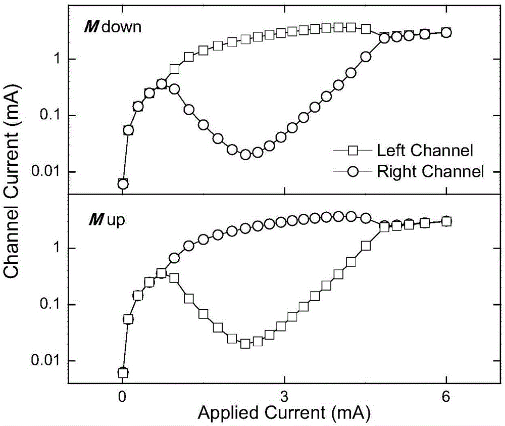
[0027] In the magnetic logic device 100, one magnetic unit 101 and two differential negative conductance units 131 are combined as follows: figure 1 connected in a manner to form a magnetic logic device 100. The current flows in from the electrode 121 at the top, and flows out from the electrodes 122 and 123 on the left and right. In a specific loading current range, the output ...

Embodiment 2

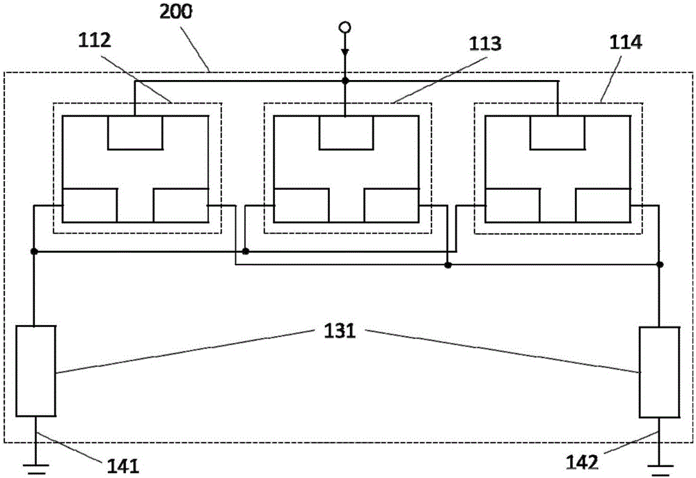
[0030] Connect the magnetic unit 112, the magnetic unit 113 and the magnetic unit 114 in parallel, and then connect the two differential negative conductance units 131 as follows image 3 The connections shown constitute a magnetic logic device 200 capable of implementing reconfigurable logic operations of "AND", "OR", "NOR" and "NAND". For each magnetic unit, current flows in from the top electrode 121 and flows out from the left and right electrodes. It is stipulated that the magnetization direction of the magnetic thin film is perpendicular to the film surface, and the logic input "1" is downward, the logic input "0" is upward, the channel current is high current, the logic output is "1", and the low current is the logic output "0". In this instance, an input current of 2.2mA is provided, and four logic operations are realized by controlling the logic input and selecting the logic output channel. When the input of magnetic unit 112 is "1", the logic inputs (a, b) of magnet...

Embodiment 3

[0032] On the basis of the magnetic logic device 200 in Embodiment 1, the magnetic unit 115 and the magnetic unit 116 are respectively connected in series to the left channel 141 and the right channel 142 to form a magnetic logic device 300 (such as Figure 4 ), so that the reading, logic operation and writing of non-volatile information are completed in the same step. Figure 4 131 in the differential negative conductance unit. For the magnetic unit 115 and the magnetic unit 116, under the horizontal applied magnetic field 151, when the electric current flows from its left electrode to the right electrode, the magnetization direction of the magnetic film will reverse (as Figure 5 ). When the applied magnetic field 151 is 50 mT, the magnetization switching current value is about 1 mA.

[0033] Before performing the logic operation, a current of 2mA from right to left is passed through the magnetic unit 115 and the magnetic unit 116 to make the magnetization direction of the...


PUM


Abstract

The invention belongs to the technical field of spintronics and devices, and particularly relates to a reconfigurable magnetic logic device and a preparation method therefor. The magnetic logic device comprises a magnetic unit and a differential negative conductive device; the magnetic unit comprises three electrodes which are manufactured on the surface of a magnetic thin film based on a certain geometrical shape; the electrodes are divided into input electrodes and output electrodes; and one end of the differential negative conductive device is connected with the output electrodes of the magnetic unit while the other end of the differential negative conductive device is grounded. The magnetic logic device can realize four kinds of basic logic operation at a room temperature in a low electric field; and in addition, the magnetic logic device has the characteristics of quite high output ratio and low working magnetic filed. The magnetic logic device is industrially compatible with a silicon-based semiconductor, excellent in performance, simple in structure, moderate in raw material cost, and environment-friendly.

Description

technical field [0001] The invention belongs to the technical field of spintronics and devices, and in particular relates to a reconfigurable magnetic logic device and a preparation method thereof. Background technique [0002] Traditional electronic computers are built on the basis of von Neumann structure, because storage and logic are separated from each other in its hardware structure, its development has encountered a bottleneck. Emerging magnetic logic devices, with their reconfigurable logic and combination with nonvolatile memory, are expected to break through this bottleneck. [0003] Current magnetoelectric logic devices are mainly divided into two categories, one is spin logic devices based on spin-dependent transport in magnetic materials, and the other is magnetic field logic devices based on asymmetric magnetoresistance effect in nonmagnetic semiconductors. However, although the existing magnetic logic devices have their own characteristics, they still face a ...

Claims


Application Information

Patent Timeline
Patent Type & Authority Applications(China)
IPC IPC(8): H01L43/00H01L43/08H01L43/12G11C11/14G11C11/15G11C11/16
CPCG11C11/14G11C11/15G11C11/16H10N50/00H10N50/01H10N50/10
Inventor 罗昭初章晓中卢子尧熊成悦孙雯
Owner TSINGHUA UNIV
Why Eureka
Try Eureka