
Impact power tool with a precision controlled drive system

a technology of precision control and power tools, applied in the field of impact power tools, can solve the problems of insufficient power range of combination systems, insufficient consumption of valuable and limited inventory space on a craftsman's work bench, and insufficiently meeting the needs of prior art impact power tools, etc., to achieve the effect of improving the stroke speed of a work tool, improving the precision control drive system, and improving the housing design

Active Publication Date: 2008-08-19
GLENDO
View PDF8 Cites 5 Cited by
  • Summary
  • Abstract
  • Description
  • Claims
  • Application Information

AI Technical Summary

Benefits of technology

"The present invention is an improved impact power tool that solves problems and limitations of previous tools. It has several advancements, including a better housing design and a precision controlled drive system that allows for faster and more powerful strokes of the work tool. The tool also has an improved air storage tank and an improved housing design for better low-speed impact and high-speed response. Overall, the invention provides a more efficient and effective impact power tool."

Problems solved by technology

These desires are not being adequately met with the prior art impact power tools.
In fact, craftsman desiring to perform multiple crafting applications that each require a different, wide range of power output must currently utilize multiple impact power tool systems to accomplish their tasks and even then, the combination of systems does not adequately address their desired ranges of power.
Current impact power tool systems, particularly the use of multiple systems, undesirably consume valuable and limited inventory space on a craftsman's work bench.
Prior art impact power tools are also subject to other problems and limitations.
Such response time is simply lacking in prior art impact power tools.
This problem is further frustrated by the craftsman's frequent “over-driving” of the tool—for example, when the craftsman is searching for the desired stroke speed or impact energy that is outside of the limits of the prior art tools.

Method used


Image

  • Impact power tool with a precision controlled drive system
  • Impact power tool with a precision controlled drive system
  • Impact power tool with a precision controlled drive system

Examples


Embodiment Construction

[0031]The preferred forms of the invention described above are to be used as illustration only and should not be utilized in a limiting sense in interpreting the scope of the present invention. Obvious modifications to the exemplary embodiments, as hereinabove set forth, could be readily made by those skilled in the art without departing from the spirit of the present invention.

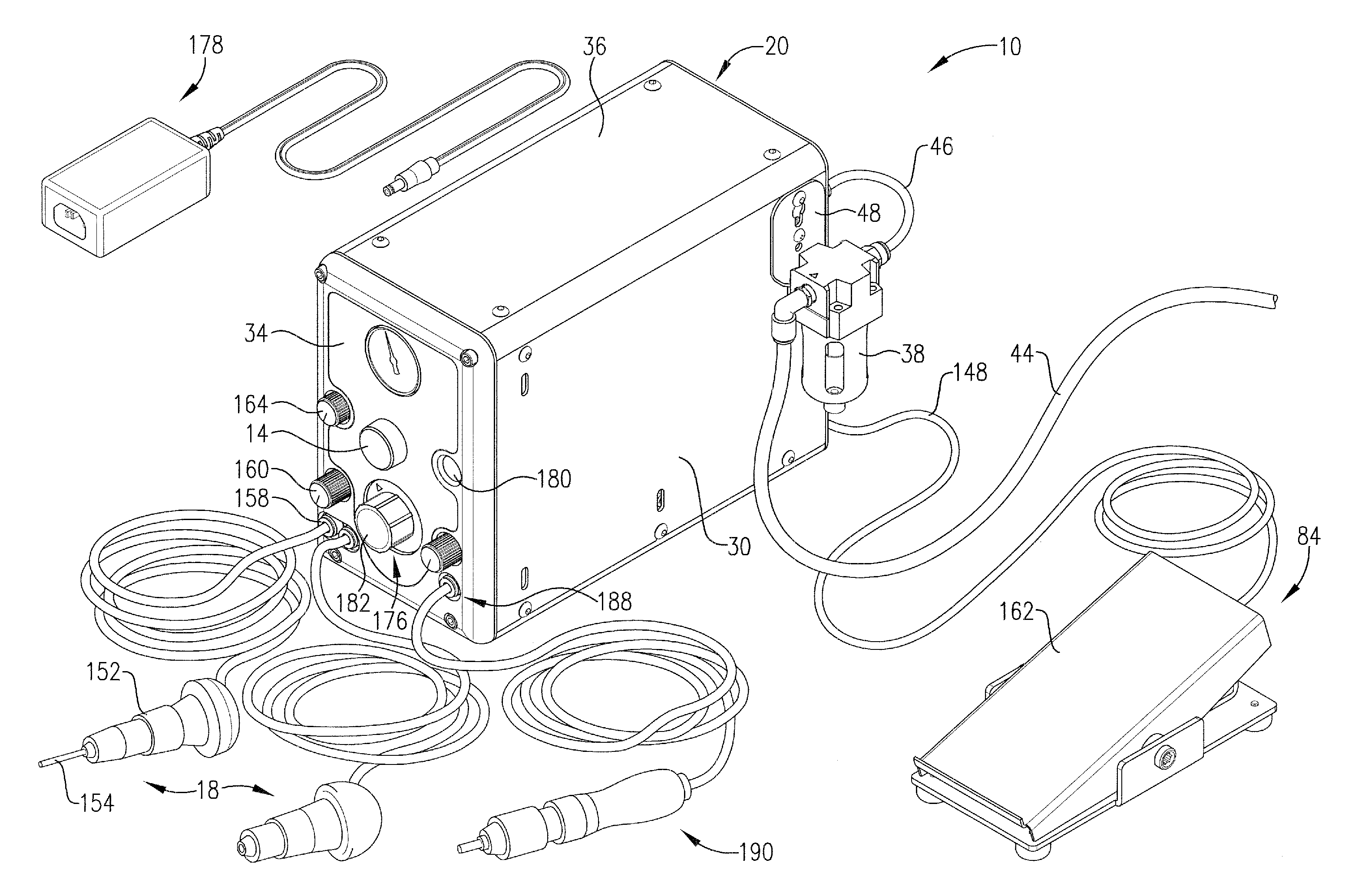
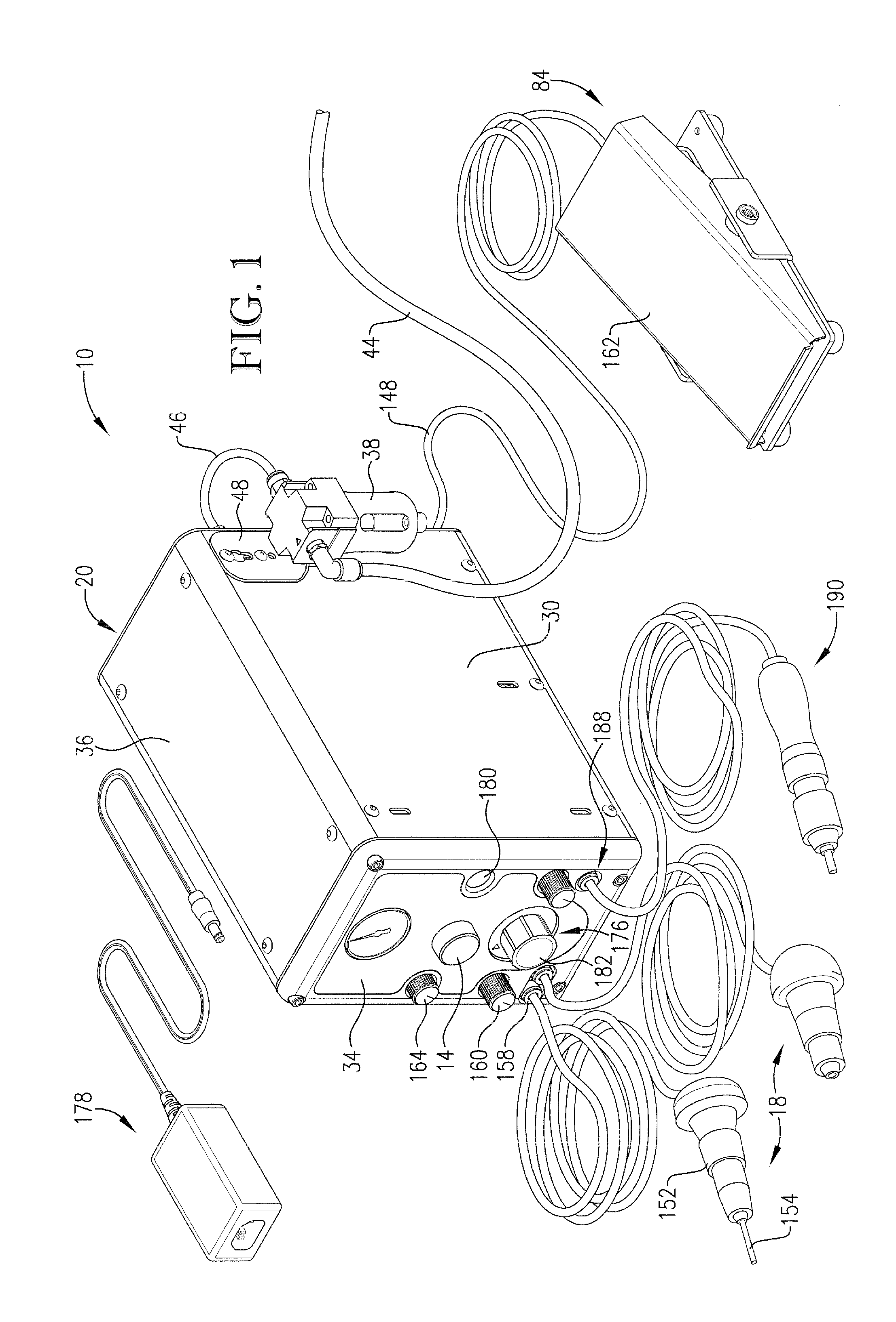
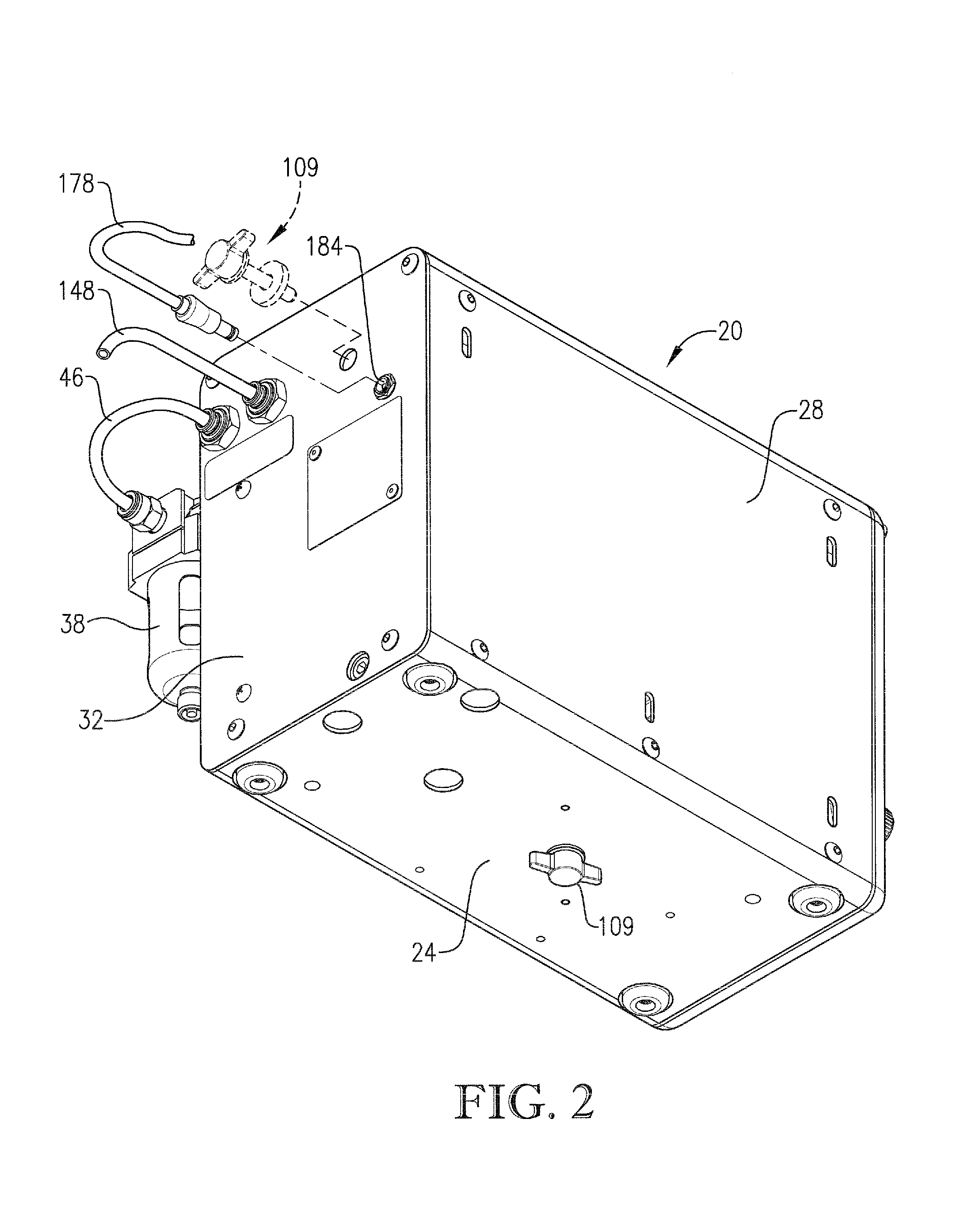
[0032]The present invention is an impact power tool 10 for use in delicate hand working operations, such as detailed, precise, and fine engraving, carving, and stone setting work. An embodiment of the impact power tool comprises an air delivery system 12 operable to communicate with a pressurized air source (not shown); a drive assembly 16 operable to receive air from the pressurized air source via the air delivery system 12; a hand held device 18 in driven communication with the drive assembly 16 and for performing the delicate hand working operations; and a housing 20 for storage of the air delivery system ...


PUM

PropertyMeasurementUnit
air pressureaaaaaaaaaa
pressureaaaaaaaaaa
pressuresaaaaaaaaaa

Abstract

An improved impact power tool for carving and engraving an article comprises an air delivery system operable to communicate with a pressurized air source; a drive assembly operable to receive air from the pressurized air source via the air delivery system; a hand held device in driven communication with the drive assembly; and a housing for storage of the air delivery system and drive assembly. The tool includes an improved valve design, a throttle bias valve, and an air storage tank housed within the housing, and an improved housing construction. The improved valve design and air storage tank enable greater stroke speeds of a work tool over a wider power range while also improving the crispness and speed of the impact reaction time over the entire range. The throttle bias valve is in communication with an additional exhaust path, such that the bias valve allows improved control of the hand held device and improved operation over a wider range of air pressures.

Description

RELATED APPLICATION[0001]This application claims the benefit of U.S. Provisional Application No. 60 / 595,764, filed Aug. 3, 2005, and entitled IMPACT POWER TOOL WITH PRECISION CONTROLLED DRIVE SYSTEM, which is hereby incorporated by reference herein.BACKGROUND OF THE INVENTION[0002]1. Field of the Invention[0003]The present invention relates generally to impact power tools. More specifically, the present invention concerns an impact power tool, such as a pneumatically powered, rotary valve controlled tool, for use in delicate hand working operations, such as detailed, precise, and fine engraving, carving, and stone setting work.[0004]2. Discussion of Prior Art[0005]Delicate hand working operations, such as detailed, precise, and fine engraving, carving, and cutting on metals, woods, stones, and the like, as well as stone setting work require an impact tool that delivers a low impact energy level for each stroke of the tool and that is capable of delivering such low impact strokes at ...

Claims


Application Information

Patent Timeline
Patent Type & Authority Patents(United States)
IPC IPC(8): B25D9/14
CPCB44B5/00B25D9/26B25D9/16B25D2250/181B25D2250/201B25D2250/121B25D2216/0015
Inventor GLASER, DONALD J.TIDWELL, LON C.
Owner GLENDO
Learn More