Process control architecture with hydrodynamic correction

a technology of hydrodynamic correction and process control, applied in the direction of sealing/packing, instruments, borehole/well accessories, etc., can solve the problems of blenders not being able to completely fill the annulus, the cement setting is too fast, and the blender can possibly run empty, so as to achieve the effect of providing stability to the overall system

Inactive Publication Date: 2008-08-19
HALLIBURTON ENERGY SERVICES INC
View PDF6 Cites 18 Cited by
  • Summary
  • Abstract
  • Description
  • Claims
  • Application Information

AI Technical Summary

Benefits of technology

[0004]Modern hydrocarbon production and processing systems use automated equipment in many aspects of their operations. A key element of such automated operations is the process control system. Such control systems usually include sensors, which in one important function, send a signal back to a process control unit. The signal is usually a communication of a process variable or condition, such as temperature, pressure, fluid or solid flow rate, or fluid level in a container. The process control unit can perform such functions as monitoring the system or unit operations or process variables, making process decisions, energizing and de-energizing equipment, collecting and maintaining data, providing stability to the overall system, and, very importantly, ensuring the system and the unit operations comprising the system operate within desired parameters.
[0005]Sensors are often placed at specific locations within a production or processing system to provide information necessary for the control of various unit operations. The role of the sensor includes providing accurate and real-time information about a particular process variable or set of variables such that the process control unit can make decisions based on good and accurate information.
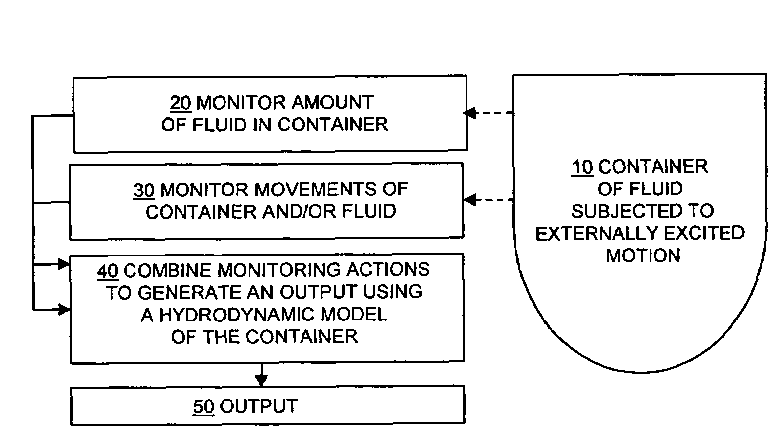
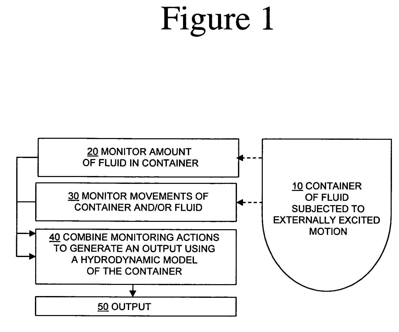
[0017]The present Application discloses new architectures for processes which involve fluid level determination in environments which can be subject to externally-excited motion. Movement of a container can cause fluid therein to slosh, and this can confuse simple measurements of the height of the fluid in the container. The present Application teaches that a hydrodynamic model of in-container fluid motion can be used to remove this source of uncertainty. This architecture can be advantageously implemented in or applied to a wide variety of conventional process control architectures, to improve the fluid amount estimations which would otherwise have been used.
[0022]The disclosed innovations, in various embodiments, provide one or more of at least the following advantages:

Problems solved by technology

Too much of, e.g. a cement-set accelerator, can result in setting the cement too quickly and not allowing it to completely fill the annulus.
Thus, if the process control system makes an under-shoot error, or is too slow in responding to a low level measurement signal from the fluid level gauge in the blender, the blender can possibly run empty, and the pump could suck and pump air into the annulus.
In another situation in which a low fluid level is sensed, the process control system might over-shoot the addition of a particular component, such as a cement-set accelerant, and seriously jeopardize the success of the cementing operation, because the cement might set-up before the annulus is completely filled.
A significant problem then arises, for example, in the cement blending operation, because the fluid level sensor in the blender can sense a low level when in-fact the blender has the correct amount of mixed cement.
As sloshing continues, the level sensor unknowingly continues to send the changing level signal to the control system, which if not corrected, will begin to make under-shoot and over-shoot errors.
Thus, averaging, damping, or lagging the control system to account for slow-moving ocean swells is not a completely adequate solution to the problem.
These factors also present the control system with differing and complex control problems.
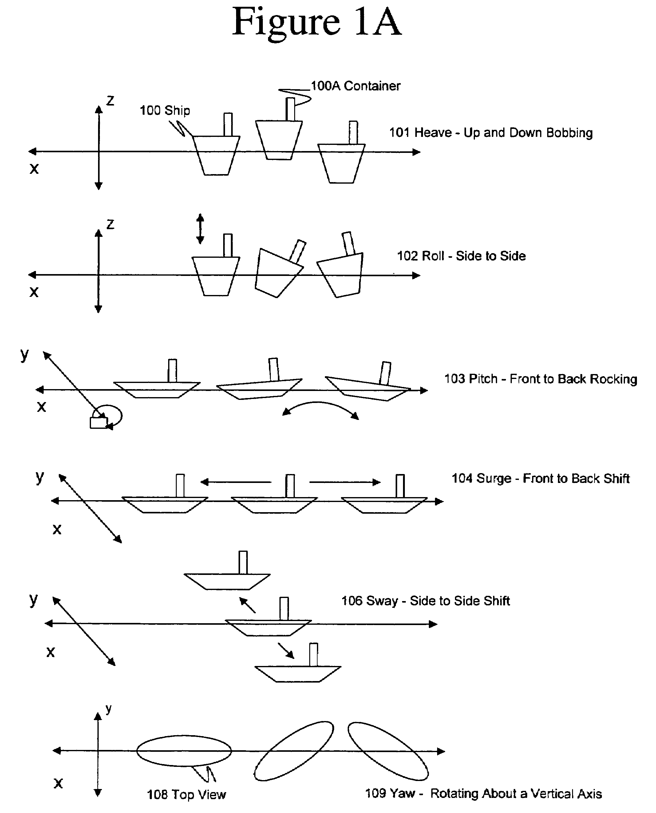
However, the size and complexity of the weights or compensating mechanical devices to correct for not just sway, but for the other five motions, represent significant engineering and other kinds of challenges.
Again, the size and weight of such containers present engineering and other challenges to account for all six motions.
Additionally, the pipes, feeders, pumps, mixers, and other equipment attached to the container or blenders would need to somehow be flexibly connected to the container being moved in response to active motion compensation, which will present additional engineering and other challenges.
Thus, solving the problem of reliably controlling processes involving fluid level control in containers subjected to externally-excited motions presents challenges, and requires solutions not adequately met by current approaches, and it remains a particular problem in off-shore equipment operations.
Movement of a container can cause fluid therein to slosh, and this can confuse simple measurements of the height of the fluid in the container.

Method used


Image

  • Process control architecture with hydrodynamic correction
  • Process control architecture with hydrodynamic correction
  • Process control architecture with hydrodynamic correction

Examples


Embodiment Construction

[0035]The numerous innovative teachings of the present Application will be described with particular reference to the presently preferred embodiment (by way of example, and not of limitation).

Physical System and Model

[0036]FIG. 2 shows a non-limiting embodiment of some possible components of an exemplary off-shore hydrocarbon well site 200 to which the present innovations can be applied. On the surface of the water, many different components are possible. In one embodiment of the present innovations, a crew ship 201 can be present. In one embodiment of the present innovations, drilling ship 203 can be present and such a ship has a drilling mud preparation processing operation on-board to which some or all of the present innovations can be applied. In one embodiment of the present innovations, fracturing ship 205 can be present and has a fracturing fluid preparation processing operation to which some or all of the present innovations can be applied. In one embodiment of the present i...


PUM


Abstract

Methods and systems for controlling processes related to the amount of fluid in a container subjected to externally-excited motions. Fluid level sensor measurements in processing tanks on-board boats are confused by ocean waves and swells. A hydrodynamic model of a fluid in a tank can be constructed using non-linear dynamic model algorithms with inputs such as multi-axis accelerations, fluid viscosity, and apparent level measurements. The model can be used to filter-out boat motion disturbances to obtain a corrected level of the fluid in the tank. The corrected fluid level signal can be further processed using a dynamic model of the tank and associated input and output flow rates in a closed loop observer. The methods and systems are especially advantageous for offshore equipment such as cementing and fracturing ships.

Description

BACKGROUND AND SUMMARY OF THE INVENTION[0001]The present application relates to systems and methods for process control, and more particularly to control of processes related to the amount of fluid in a container subject to externally-excited motions, and most especially to control of processes such as storing and blending of fluids and solids when such processes are conducted aboard a waterborne apparatus.[0002]The following paragraphs contain some discussion, which is illuminated by the innovations disclosed in this Application, and any discussion of actual or proposed or possible approaches in these paragraphs does not imply that those approaches are prior art.[0003]Background: Process Control of Fluid Level[0004]Modern hydrocarbon production and processing systems use automated equipment in many aspects of their operations. A key element of such automated operations is the process control system. Such control systems usually include sensors, which in one important function, send...

Claims


Application Information

Patent Timeline
Patent Type & Authority Patents(United States)
IPC IPC(8): G06F19/00
CPCB28C7/0418G01F23/0076E21B33/13B28C9/004G01F23/804
Inventor MAZROOEE, MEHDIDYKSTRA, JASON D.
Owner HALLIBURTON ENERGY SERVICES INC
Why Eureka
Try Eureka