Fuel gas production apparatus and method of starting operation of fuel gas production apparatus

a technology of fuel gas production apparatus and fuel gas, which is applied in the direction of hydrogen separation using solid contact, electrochemical generator, separation process, etc., can solve the problem of thermal load applied to the catalyst combustor b>4

Inactive Publication Date: 2008-08-26
HONDA MOTOR CO LTD
View PDF7 Cites 10 Cited by
  • Summary
  • Abstract
  • Description
  • Claims
  • Application Information

AI Technical Summary

Benefits of technology

[0012]A main object of the present invention is to provide a fuel gas production apparatus and a method of starting operation of the fuel gas production apparatus in which operation of the fuel gas production apparatus is started efficiently and suitably regardless of the operation suspension period of a pressure swing adsorption mechanism.
[0018]According to the present invention, since the valve positions of the cleaning valves and / or the off gas valves are adjusted, regardless of the length of the operation suspension period immediately before operation of the pressure swing adsorption mechanism, it is possible to prevent the shortage of the off gas calories or the like due to the decrease in the amount of the cleaning gas in the cleaning step. Further, since the off gas is not discharged excessively in the desorption step, it is possible to prevent the thermal load from being imposed on the heating unit. Thus, operation of the fuel gas production apparatus is started efficiently and suitably. The term “cleaning step” herein means the pressure reduction step in each tower of the pressure swing adsorption mechanism.

Problems solved by technology

Thus, thermal load is applied to the catalyst combustor 4 undesirably.

Method used


Image

  • Fuel gas production apparatus and method of starting operation of fuel gas production apparatus
  • Fuel gas production apparatus and method of starting operation of fuel gas production apparatus
  • Fuel gas production apparatus and method of starting operation of fuel gas production apparatus

Examples


first embodiment

[0074]Firstly, a starting method according to the present invention will be described with reference to a flow chart shown in FIG. 9.

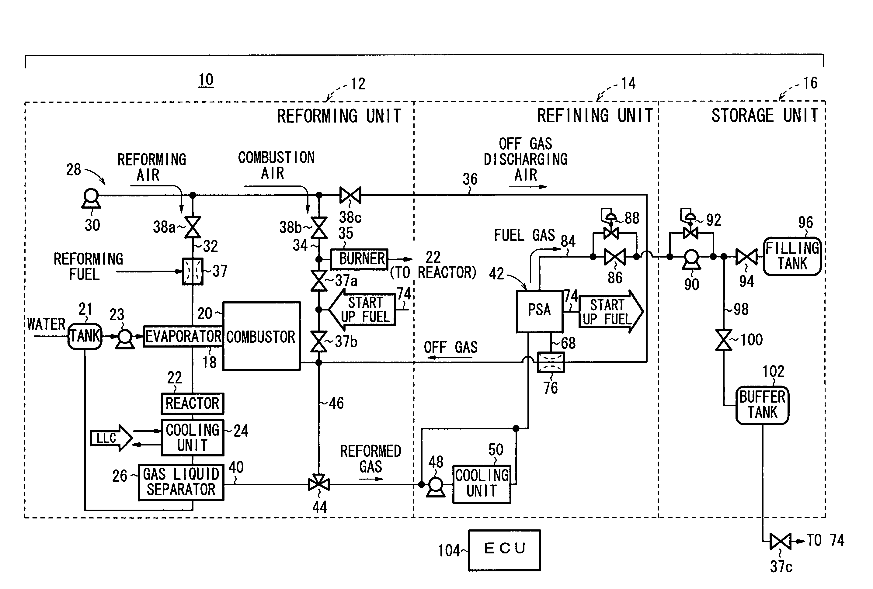
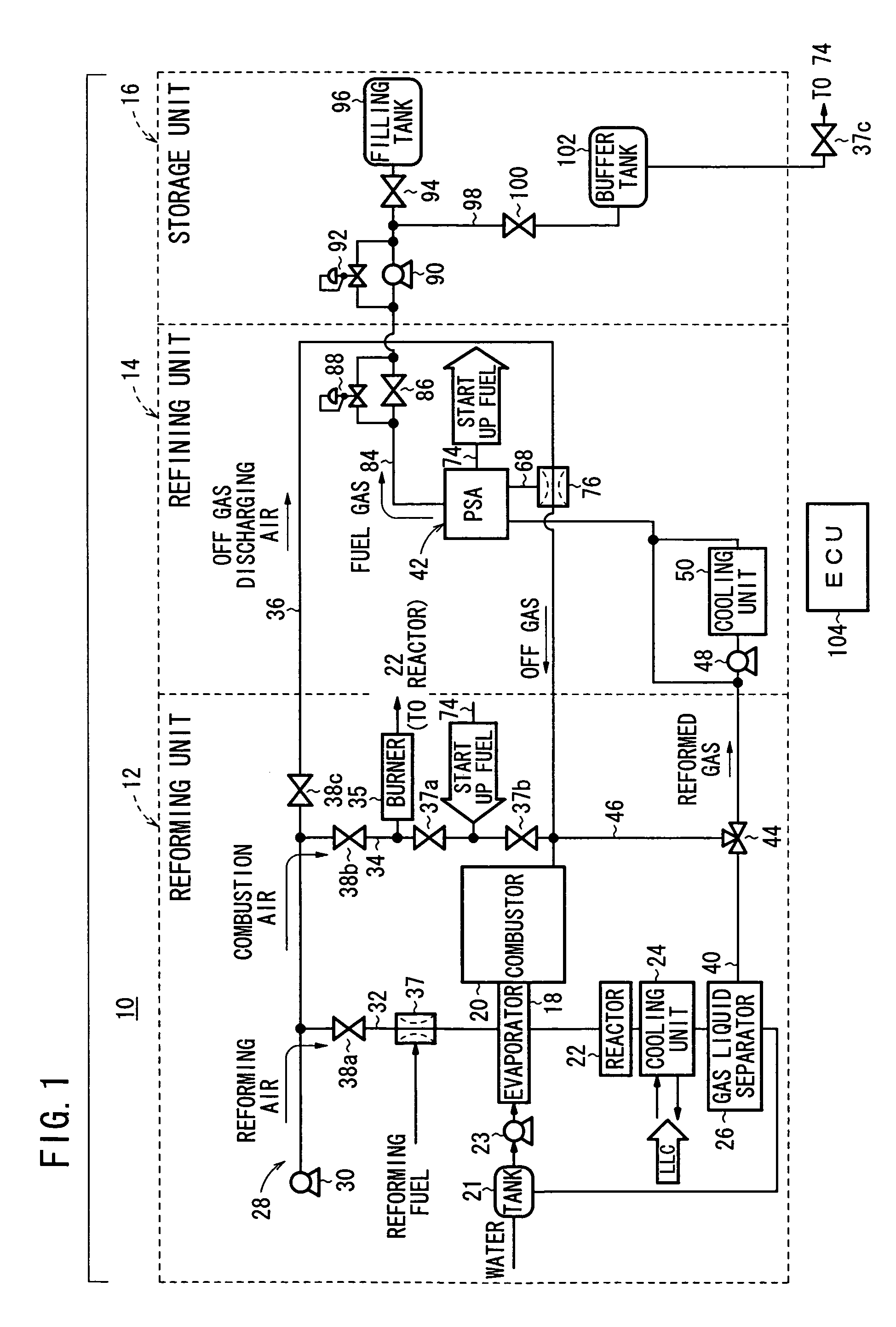
[0075]In the home fuel gas production system 10, a suspension period of the PSA mechanism 42 is read by a timer (not shown) provided in the ECU 104 (step S1). The ECU 104 determines initial valve positions of the cleaning valves 82a through 82c and the off gas valves 66a through 66c based on the read suspension period using predetermined valve position determination maps (see FIGS. 10 and 11).

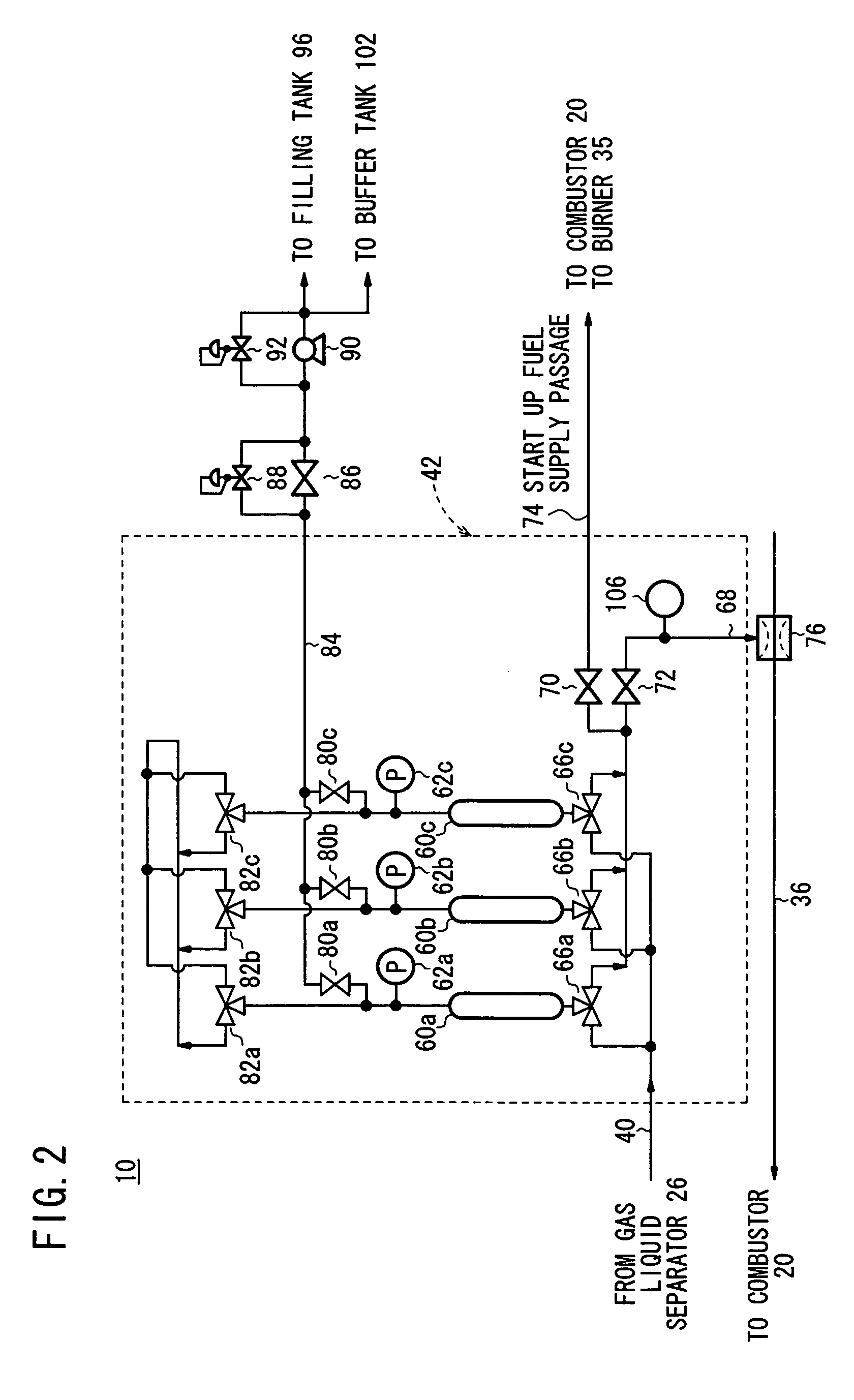
[0076]When the suspension period of the PSA mechanism 42 read by the timer becomes long, concentration of the impurity gas passing through the cleaning valves 82a through 82c becomes high. Therefore, as shown in FIG. 10, as the suspension period gets longer, the initial valve positions of the cleaning valves 82a through 82c are determined such that the cleaning valves 82a through 82c are opened widely, i.e., the openings of the cleaning valves 82a through 82c get ...

second embodiment

[0083]Next, a starting method according to the present invention will be described with reference to a flow chart shown in FIG. 12.

[0084]In the second embodiment, firstly, operation of the home fuel gas production system 10 is started (step S11), and the cleaning step is started. For example, the pressure drop in the adsorption tower 60c at the time of cleaning is read (step S12). Based on the tower pressure drop, initial valve positions of the cleaning valves 82a through 82c and initial valve positions of the off gas valves 66a through 66c are determined (step S13).

[0085]The initial positions of the cleaning valves 82a through 82c based on the tower pressure drop are determined using a valve position determination map shown in FIG. 13. When the impurity concentration in the cleaning gas passing through the cleaning valves 82a through 82c is high, the cleaning gas does not pass through the cleaning valves 82a through 82c smoothly, and the tower pressure drop is small. Therefore, the...

third embodiment

[0091]Next, a starting method will be described with reference to a flow chart shown in FIG. 15.

[0092]In the third embodiment, after operation of the home fuel gas production system 10 is started (step S21), the increase in the temperature of the combustor 20 at the time of cleaning is read (step S22). Then, based on the increase in the temperature of the combustor 20, valve positions of the cleaning valves 82a through 82c and valve positions of the off gas valves 66a through 66c are determined using valve position determination maps shown in FIGS. 16 and 17.

[0093]As shown in FIG. 16, when the increase in the temperature of the combustor 20 is small, the cleaning gas does not flow smoothly. Therefore, the initial positions of the cleaning valves 82a through 82c are determined such that the cleaning valves 82a through 82c are opened widely, i.e., the openings of the cleaning valves 82a through 82c are large. Further, as shown in FIG. 17, when the increase in the temperature of the c...


PUM

PropertyMeasurementUnit
of timeaaaaaaaaaa
pressureaaaaaaaaaa
pressure dropaaaaaaaaaa

Abstract

A PSA mechanism has adsorption towers. Cleaning valves and off gas valves are connected to the adsorption towers. Valve positions of at least either the cleaning valves or the off gas valves are determined based on an operation suspension period of the PSA mechanism or internal conditions which vary depending on the operation suspension period.

Description

BACKGROUND OF THE INVENTION[0001]1. Field of the Invention[0002]The present invention relates to a fuel gas production apparatus for reforming a hydrogen-containing fuel into a reformed gas, and refining the reformed gas to produce a hydrogen-rich fuel gas. Further, the present invention relates to a method of starting operation of the fuel gas production apparatus.[0003]2. Description of the Related Art[0004]For example, hydrogen production apparatuses (fuel gas production apparatuses) for reforming a hydrocarbon fuel such as natural gas or a hydrogen-containing fuel such as an alcohol (e.g., methanol) into a hydrogen-containing gas (reformed gas), and refining the hydrogen-containing gas to produce a fuel gas supplied to a fuel cell or the like are adopted conventionally.[0005]For example, Japanese Laid-Open Patent Publication No. 2002-20102 discloses a hydrogen production apparatus shown in FIG. 21. The hydrogen production apparatus includes a compressor 1, a hydrodesulfurization...

Claims


Application Information

Patent Timeline
Patent Type & Authority Patents(United States)
IPC IPC(8): C01B3/32B01D53/02B01D53/12B01D59/26B01D53/04B01D53/047C01B3/34C01B3/38C01B3/56C10K1/32
CPCC01B3/34C01B3/56B01D53/047B01D53/0438C01B2203/1604B01D53/053B01D2256/16B01D2258/0208B01D2259/40007B01D2259/40009B01D2259/4003B01D2259/40037B01D2259/40052B01D2259/40067B01D2259/403B01D2259/4566C01B2203/0205C01B2203/043C01B2203/0475
Inventor SUMI, HIDEAKIOKADA, HIKARUHANAI, SATOSHIMACHIDA, HIROSHI
Owner HONDA MOTOR CO LTD
Why Eureka
Try Eureka