System and method for analysis and transformation of layouts using situations

a technology of situation analysis and layout, applied in the field of systems, methodologies and technologies for the analysis and transformation of integrated circuit layouts using situations, can solve the problems of opc problem significant for its complexity, single mask design propagating to the complete failure of an entire design, etc., to achieve efficient situation extraction, efficiently performing situation extraction, and efficient performing situation extraction

Active Publication Date: 2008-08-26
CADENCE DESIGN SYST INC
View PDF5 Cites 72 Cited by
  • Summary
  • Abstract
  • Description
  • Claims
  • Application Information

AI Technical Summary

Benefits of technology

[0019]FIG. 4 illustrates a flow diagram for efficiently performing a situation extraction based on corners according to certain embodiments of the present invention;
[0020]FIG. 5 illustrates a flow diagram for efficiently performing a situation extraction based on edges according to certain embodiments of the present invention;
[0021]FIG. 6 illustrates a flow diagram for efficiently performing a situation extraction based on cells according to certain embodiments of the present invention;

Problems solved by technology

The impact of even small errors in the design of a single mask can propagate to the complete failure of an entire design.
Additionally, as diffraction-limited optical systems have become implemented in semiconductor manufacturing, what is printed on the wafer may not be what was designed on the mask.
The OPC problem is significant for its complexity.
However, OPC involves using today's processors to design tomorrow's processors, which means that the problem complexity scales with the speed to today's processors.
In fact, the OPC complexity may scale more quickly than the current CPU speeds are increasing because of additional factors such as an increasing number of mask (i.e., metal) layers.

Method used


Image

  • System and method for analysis and transformation of layouts using situations
  • System and method for analysis and transformation of layouts using situations
  • System and method for analysis and transformation of layouts using situations

Examples


Embodiment Construction

[0030]The present invention will now be described in detail with reference to the drawings, which are provided as illustrative examples of the invention so as to enable those skilled in the art to practice the invention. Notably, the figures and the examples below are not meant to limit the scope of the present invention. Where certain elements of the present invention can be partially or fully implemented using known components (or methods), only those portions of such known components (or methods) that are necessary for an understanding of the present invention will be described, and the detailed descriptions of other portions of such known components (or methods) will be omitted so as not to obscure the invention. Further, the present invention encompasses present and future known equivalents to the components referred to herein by way of illustration.
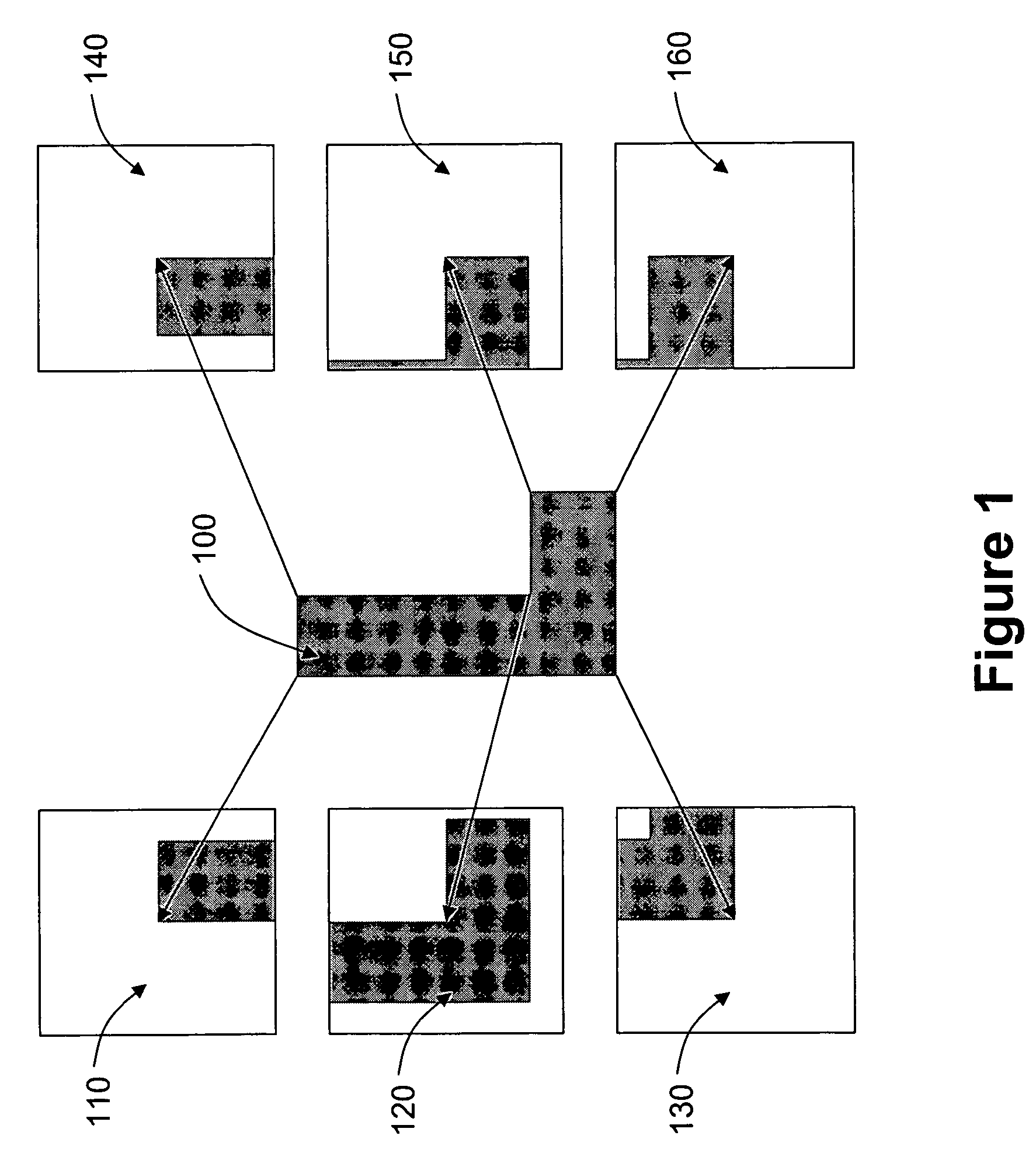
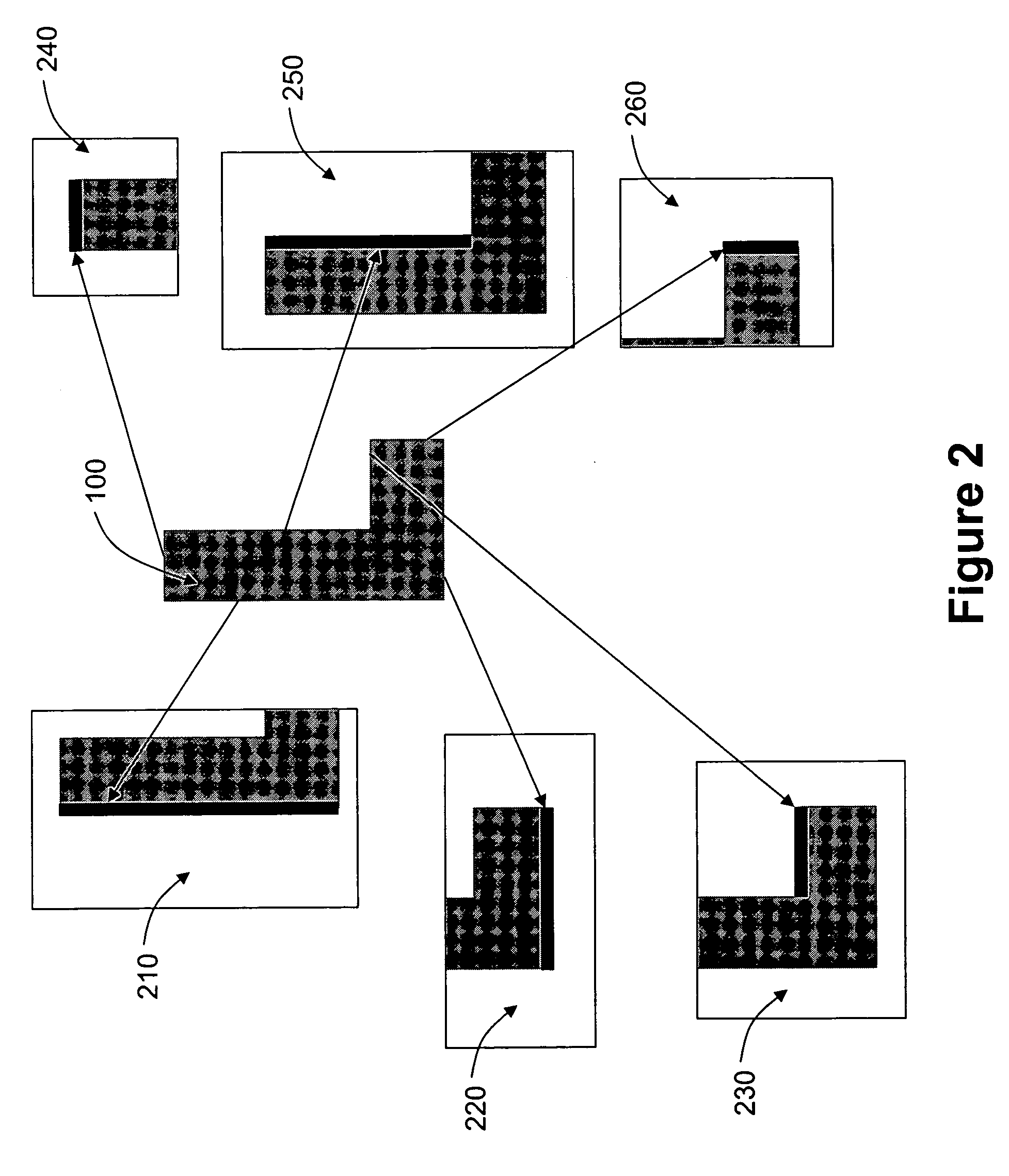
Situations Defined

[0031]A layout is a collection of shapes. A situation is a configuration of shapes or cell instances. A layout c...


PUM


Abstract

Systems, methodologies and technologies for the analysis and transformation of integrated circuit layouts using situations are disclosed. A method for transforming an integrated circuit (IC) layout includes recognizing shapes within the IC layout, identifying features for each of the shapes and extracting situations for the respective features. Extracted situations can be used to improve optical proximity correction (OPC) of the IC layout. This improved OPC includes extracting the situations, simulating the situations to determine a set of the situations identified for modification based on failing to satisfy a desired OPC tolerance level, modifying the set of situations to improve satisfaction of the desired OPC tolerance level, and reintegrating the modified set of situations into the IC layout. Extracted situations can also be used to improve aerial image simulation of the IC layout. This improved aerial image simulation includes extracting the situations, simulating a subset of the situations to determine aerial images of the subset, and tiling the subset of situations to form a larger aerial image. Extracted situations can further be used to improve density analysis of the IC layout. This improved density analysis includes extracting the situations for a window of the IC layout, removing overlap from the window based on the extracted situations, calculating a density for each of the situations, and calculating a density for the window based on the density for each of the situations.

Description

CROSS-REFERENCE TO RELATED APPLICATIONS[0001]This application claims the benefit of priority from U.S. Provisional Patent Application No. 60 / 602,901, filed Aug. 18, 2004, entitled “System and Method for Augmenting Optical Proximity Correction (OPC) Using Pattern Matching,”; U.S. Provisional Patent Application No. 60 / 602,800, filed Aug. 18, 2004, entitled “System and Method for Implementing Iamge-Based Design Rules Using Pattern-Matching for Effective Design for Manufacturability of Semiconductors,”; and U.S. Provisional Patent Application No. 60 / 602,899 filed Aug. 18, 2004, entitled “System and Method for Determining Across Chip Critical Feature Variation Using Pattern Matching,” which are fully incorporated herein by reference for all purposes.[0002]This application is related to U.S. patent application Ser. No. 11 / 207,266, commonly filed herewith on Aug. 18, 2005, entitled “System and Method for Implementing Image-Based Design Rules” and having client reference CCAD-001, which is ...

Claims


Application Information

Patent Timeline
Patent Type & Authority Patents(United States)
IPC IPC(8): G06F17/50
CPCG06F17/5068G06F2217/12G06F30/39G06F2119/18Y02P90/02
Inventor GENNARI, FRANK E.LAI, YA-CHIEHMOSKEWICZ, MATTHEW W.LAM, MICHAEL C.MCINTYRE, GREGORY R.
Owner CADENCE DESIGN SYST INC
Why Eureka
Try Eureka