Solid state imager arrangements

a solid-state imager and imager technology, applied in the direction of television system scanning details, radioation control devices, television systems, etc., can solve the problems of image resolution loss and saturation

Active Publication Date: 2008-09-02
E2V TECH (UK) LTD
View PDF15 Cites 37 Cited by
  • Summary
  • Abstract
  • Description
  • Claims
  • Application Information

AI Technical Summary

Benefits of technology

[0019]The invention is most applicable to an arrangement in which a single multiplication and a single additional register are included. However, in some embodiments, a multiplication register may be associated with a plurality of additional registers, which may be arranged in parallel or in a cascade arrangement. Also, a plurality of multiplication registers, each with its own additional register or registers may be included in an arrangement to accept signal charge from a single output register. These architectures however are somewhat complicated and it is not apparent that the complexity would be offset by improved performance.

Problems solved by technology

In the previously proposed arrangement, in parts of a scene of high illumination there is a risk that the well capacities in the multiplication register can be exceeded, leading to saturation and loss of image resolution.

Method used


Image

  • Solid state imager arrangements
  • Solid state imager arrangements
  • Solid state imager arrangements

Examples


Embodiment Construction

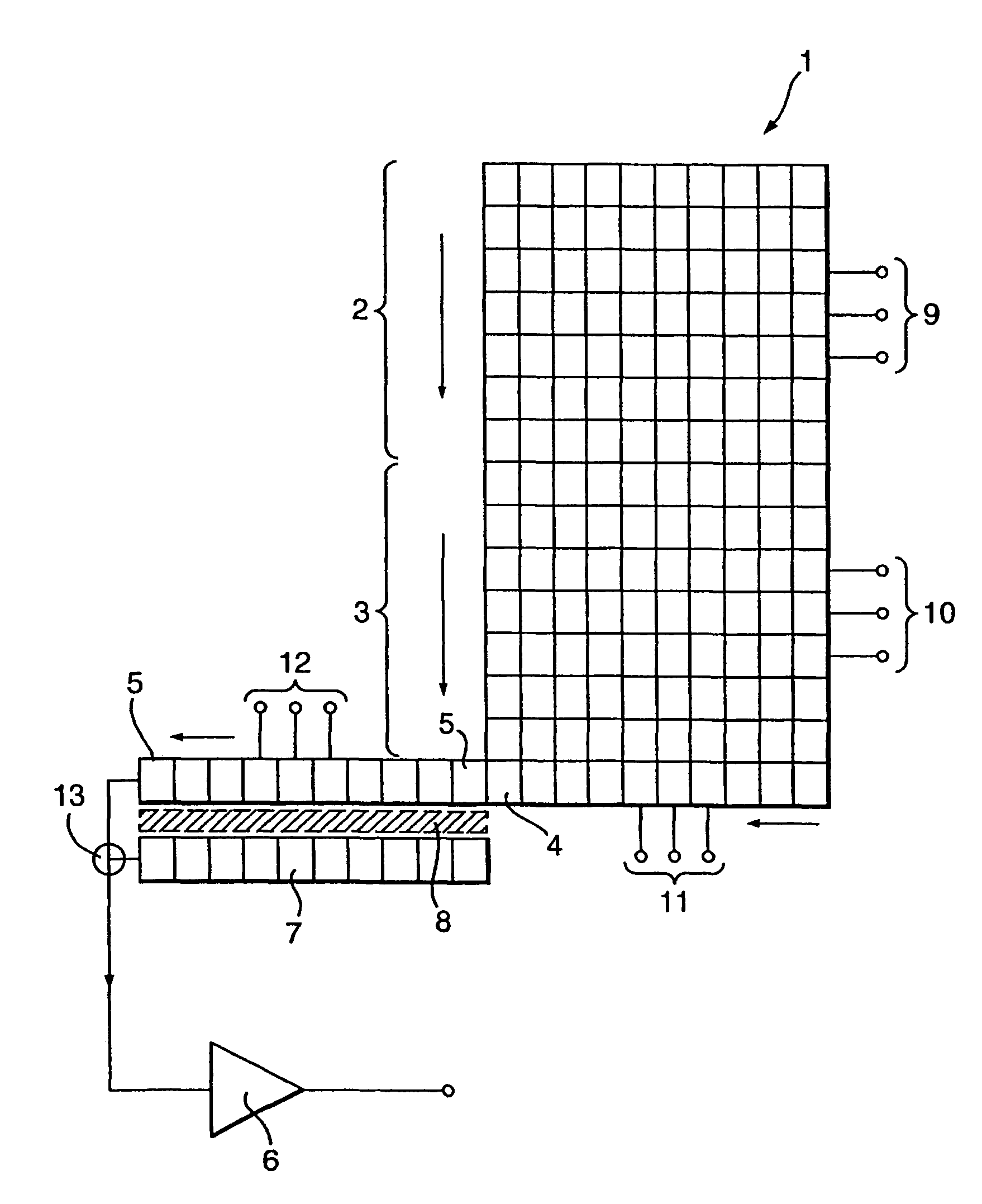
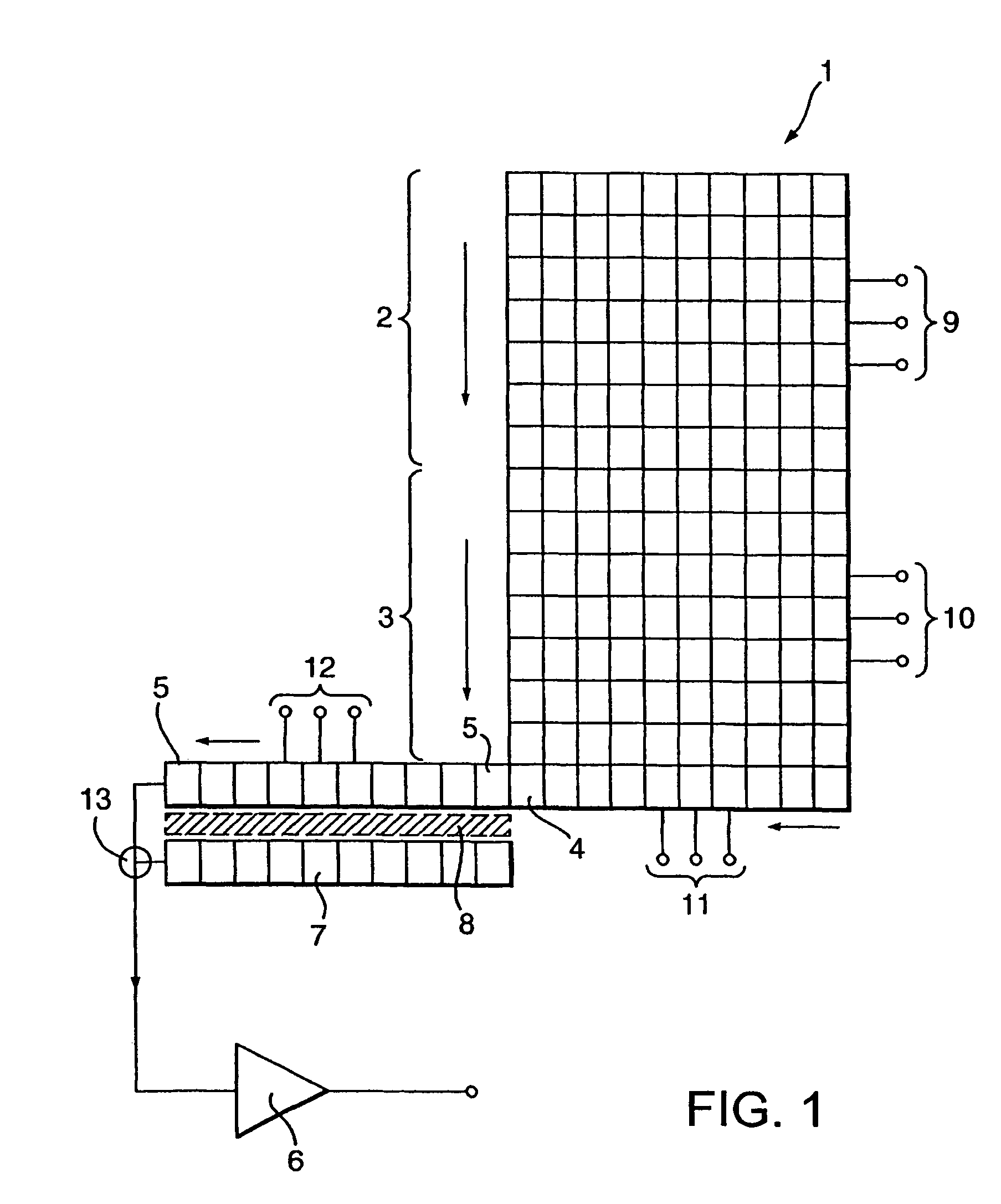
[0029]The embodiments of the invention all involve the use of a multiplication register for multiplying signal charge from a solid-state imager and an additional register arranged to receive excess charge. The purpose of the arrangement is to provide a greater dynamic range by providing gain to small levels of charge (low light levels) whilst avoiding providing too much gain to higher levels of charge (high light levels).

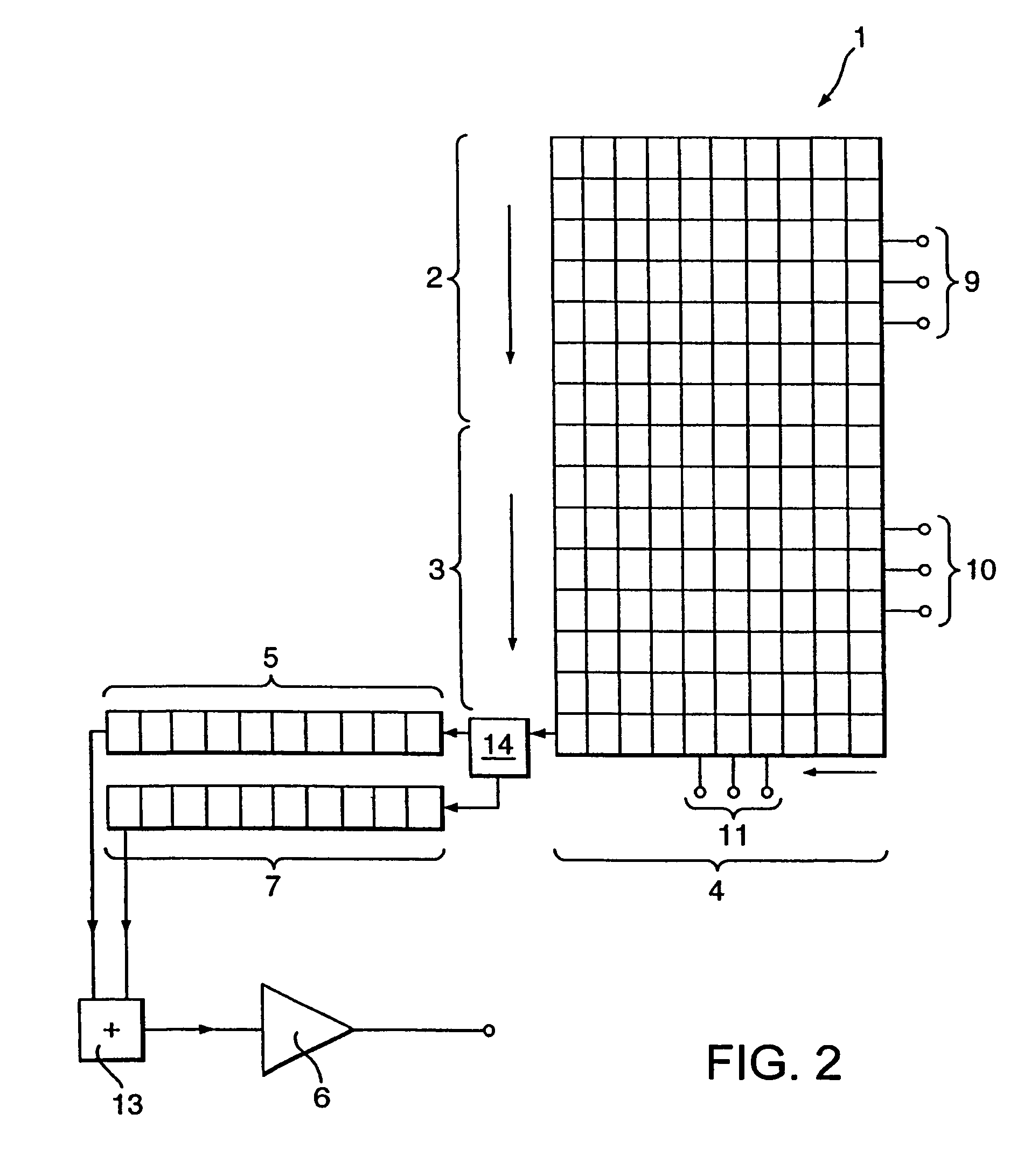
[0030]Charge is divided between the multiplication register and the additional register in two ways. First, as described later in relation to FIG. 1, excess charge transfers from each element of the multiplication register to corresponding elements of the additional register. This transfer can be by overspill over a potential barrier (FIG. 7) or by clocked elements (FIG. 8). Second, as described later in relation to FIGS. 2 and 3, excess charge is transferred to the additional register prior to applying charge to the multiplication register. The first and second met...


PUM


Abstract

A solid state imager arrangement includes an image area, an output register which receives signal charge from the image area, a separate multiplication register into which signal charge from the output register is transferred, means for obtaining signal charge multiplication by transferring the charge through a sufficiently high field in elements of the multiplication register, and an additional register into which excess signal charge is transferred.

Description

CROSS REFERENCE TO RELATED APPLICATIONS[0001]This application is a continuation-in-part of application Ser. No. 10 / 622,109, filed Jul. 18, 2003, which is a continuation of International Application No. PCT / GB02 / 00138, filed Jul. 14, 2002, and claiming priority to British Application GB 0101301.0 filed Jan. 18, 2001, to which the present application also claims priority. The disclosures of the foregoing applications, together with the disclosures of each and every U.S. and foreign patent and patent application mentioned below are incorporated herein by reference in their entirety.BACKGROUND OF THE INVENTION[0002]This invention relates to solid-state imager arrangements and more particularly to arrangements in which signal charge multiplication is implemented.[0003]In a typical charge coupled device (CCD) imager, signal charge representative of incident radiation is accumulated in an array of pixels over an image area. Following an integration period, signal charge is transferred to a...

Claims


Application Information

Patent Timeline
Patent Type & Authority Patents(United States)
IPC IPC(8): H04N3/14H04N5/335H01L27/148H01L29/768H04N5/372H04N5/376
CPCH01L29/76816H01L27/14806
Inventor POOL, PETER JAMESBELL, RAYMOND THOMAS
Owner E2V TECH (UK) LTD
Why Eureka
Try Eureka