Rotary unions, fluid delivery systems, and related methods

a technology of fluid delivery system and rotary union, which is applied in the direction of water supply installation, transportation and packaging, mechanical equipment, etc., can solve the problems of reducing the service life and affecting the operation of the rotating component. , to achieve the effect of reducing the level of debris generation, excellent performance and reducing the wear level of the componen

Active Publication Date: 2008-09-09
TEL EPION
View PDF47 Cites 10 Cited by
  • Summary
  • Abstract
  • Description
  • Claims
  • Application Information

AI Technical Summary

Benefits of technology

[0008]The present invention provides improved rotary unions and fluid delivery systems that can transfer a fluid (e.g., a process liquid) among locations that rotate relative to one another. A rotary union of the present invention can exhibit numerous advantages. For example, a rotary union according to the present invention can operate over a wide range of temperatures with excellent performance. Also, a rotary union according to the present invention can exhibit a reduced level of debris generation and / or reduced level of component wear, as compared to many other rotary unions. A rotary union of the present invention can also exhibit improved rotational stability (i.e., exhibits a reduced tendency for the rotary union to precess) and / or less resistance to rotation, as parts rotate relative to one another.
[0009]Rotary unions and fluid delivery systems according to the present invention can be particularly useful in microelectronic device applications, telecommunication device applications, and / or medical device applications where use of ultra clean reagents is common and flexibility to operate over a relatively wide range of temperatures is desirable.
[0010]Parts of a rotary union according to the present invention are assembled so that surfaces defining primary fluid pathways and drain pathways can rotate relative to each other without rotatably and / or slideably engaging each other in any significant way, if at all. Any surfaces that slideably and / or rotatably engage each other preferably are outside these fluid pathways. In preferred embodiments, rotatably and / or slideably engaging surfaces are confined to bearing(s) external to fluid pathway(s), and these bearing(s) also help to maintain the tolerances and / or spacing among components. In preferred embodiments, maintaining such tolerances and / or spacing among components is facilitated by one or more of properly locating one or more bearings, e.g., between the rotor and housing, and properly selecting component(s) materials, e.g., matching, or otherwise coordinating, the dimensional stability of materials among parts. Maintaining such tolerances can be highly desirable because a fluid flowing through the gap can be precisely controlled (e.g., minimized).
[0011]According to one aspect of the present invention, a rotary union includes a housing having a fluid path through which a fluid can be conveyed through the housing, a rotor having a fluid path through which a fluid can be conveyed through the rotor, and a post having a fluid path through which a fluid can be conveyed through the post. The rotor is rotatably coupled to the housing and the post is positioned in the rotary union in a manner effective to help fluidly couple the rotor fluid path and the housing fluid path such that a fluid can be transferred between the housing and the rotor via the post fluid path. The rotary union also includes an annular gap surrounding at least a portion of the post such that the annular gap constitutes at least a portion of a drain pathway through which a portion of fluid conveyed through the housing fluid path is drained from the rotary union.
[0015]According to another aspect of the present invention, a method of making a rotary union includes providing a housing, a rotor, a post, and at least one bearing, positioning the post in the rotary union, and rotatably coupling the rotor to the housing. The housing has a fluid path through which a fluid can be conveyed through the housing, the rotor has a fluid path through which a fluid can be conveyed through the rotor, and the post has a fluid path through which a fluid can be conveyed through the post. The post is positioned in the rotary union in a manner effective to help fluidly couple the rotor fluid path and the housing fluid path such that a fluid can be transferred between the housing and the rotor via the post fluid path. The rotor is rotatably coupled to the housing such that an annular gap surrounds at least a portion of the post such that the annular gap constitutes at least a portion of a drain pathway through which a portion of fluid conveyed through the housing fluid path is drained from the rotary union.

Problems solved by technology

For example, if a tolerance between components widens to a point beyond that intended, leaks can occur and / or components can become too loose and / or become damaged.
As another example, if a tolerance between components narrows to a point beyond that intended, the components can rub and wear and / or even prevent rotation of the rotating component(s).
One drawback of some rotary unions is that their operation is limited to relatively narrow temperature ranges.
Another drawback of some rotary unions is that debris may be generated in some applications (e.g., in the manufacture of microelectronics and / or medical devices) during even normal operations of the rotary union.
Such debris can be undesirable because it can contaminate process fluids, which in turn can contaminate manufactured goods that have stringent product specifications (e.g., microelectronic devices and medical devices).
Such debris can also be undesirable because it can cause undue wear to rotary union components and / or downstream components.

Method used


Image

  • Rotary unions, fluid delivery systems, and related methods
  • Rotary unions, fluid delivery systems, and related methods
  • Rotary unions, fluid delivery systems, and related methods

Examples


Embodiment Construction

[0026]The embodiments of the present invention described below are not intended to be exhaustive or to limit the invention to the precise forms disclosed in the following detailed description. Rather a purpose of the embodiments chosen and described is so that the appreciation and understanding by others skilled in the art of the principles and practices of the present invention can be facilitated.

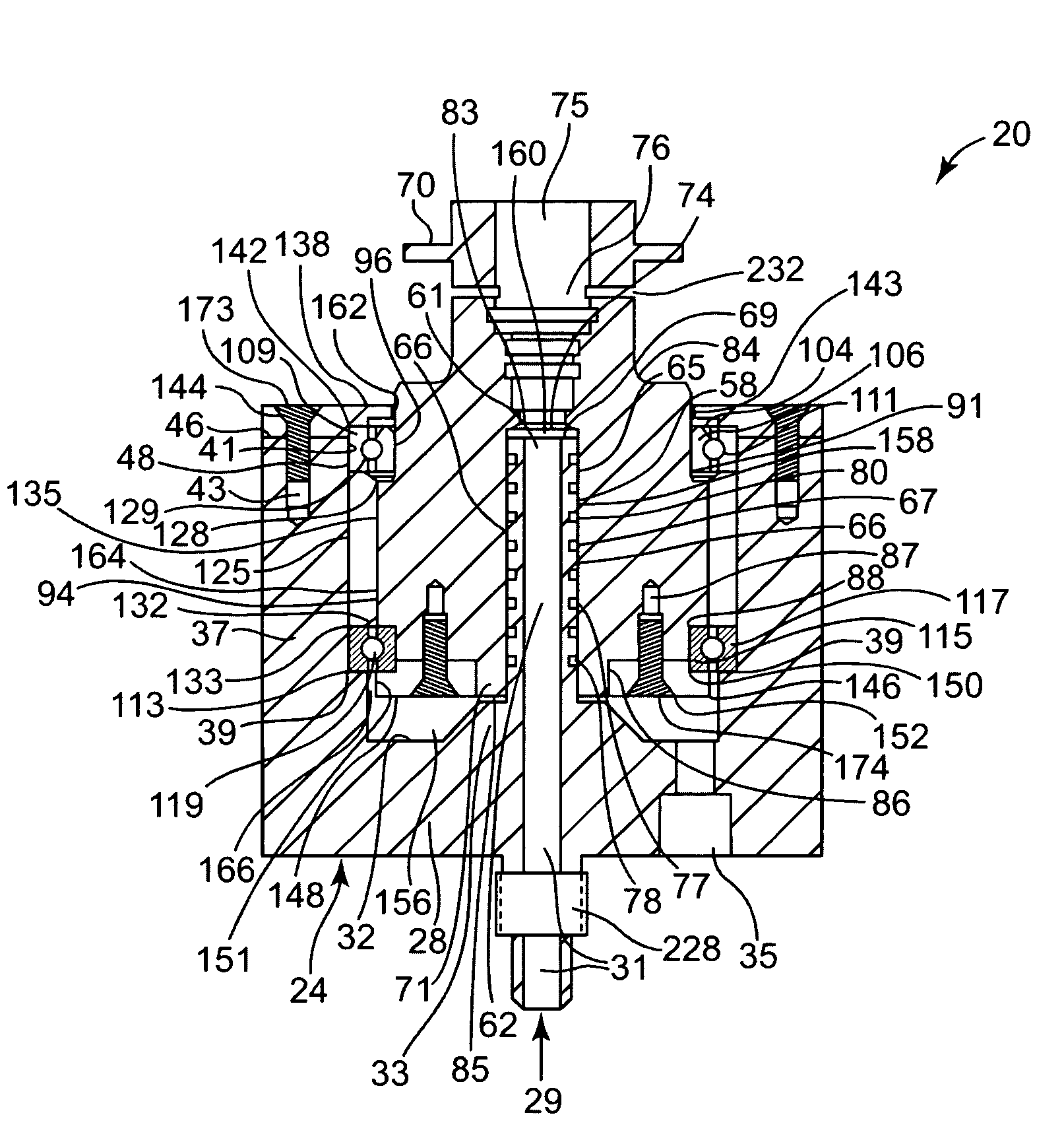
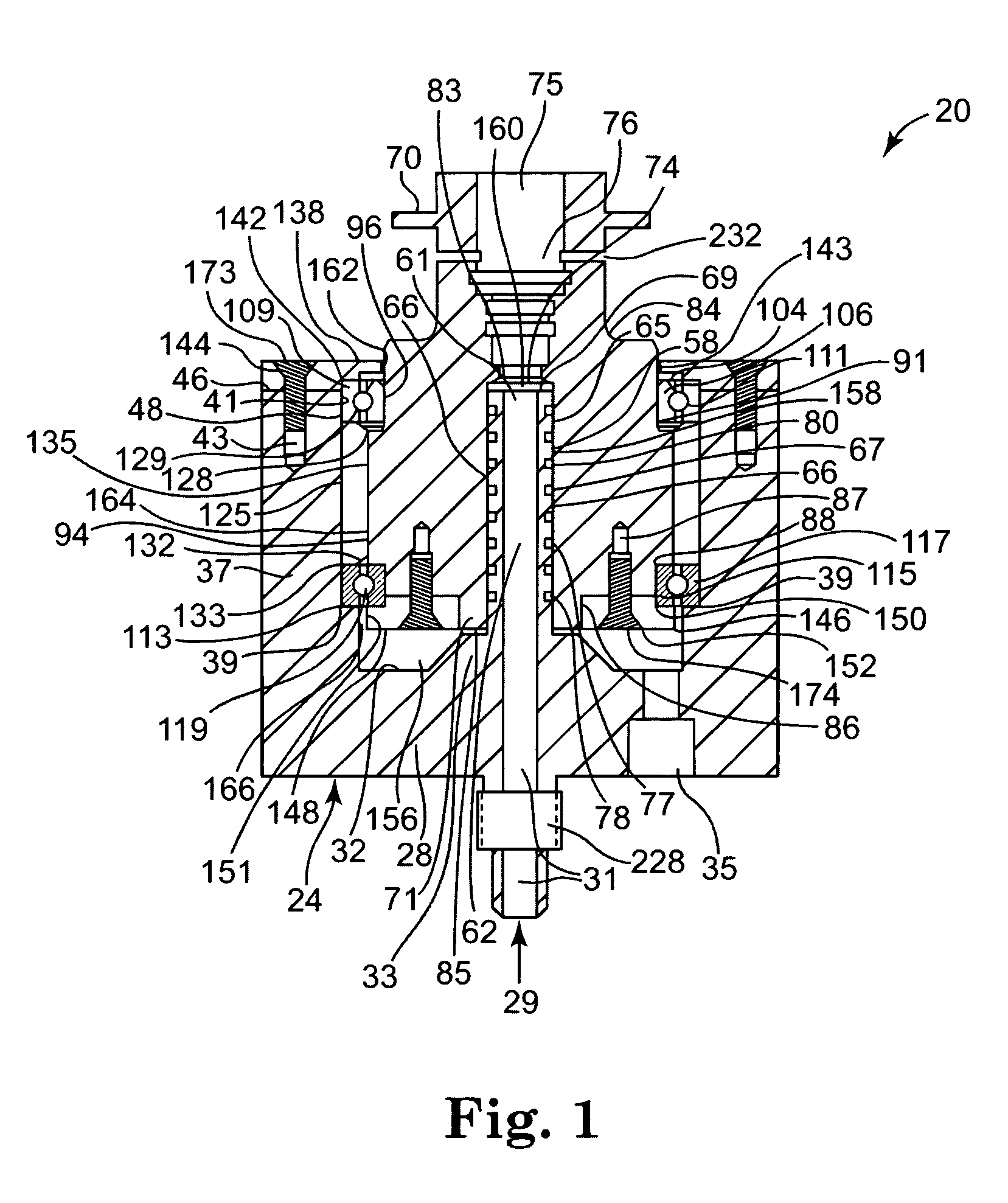
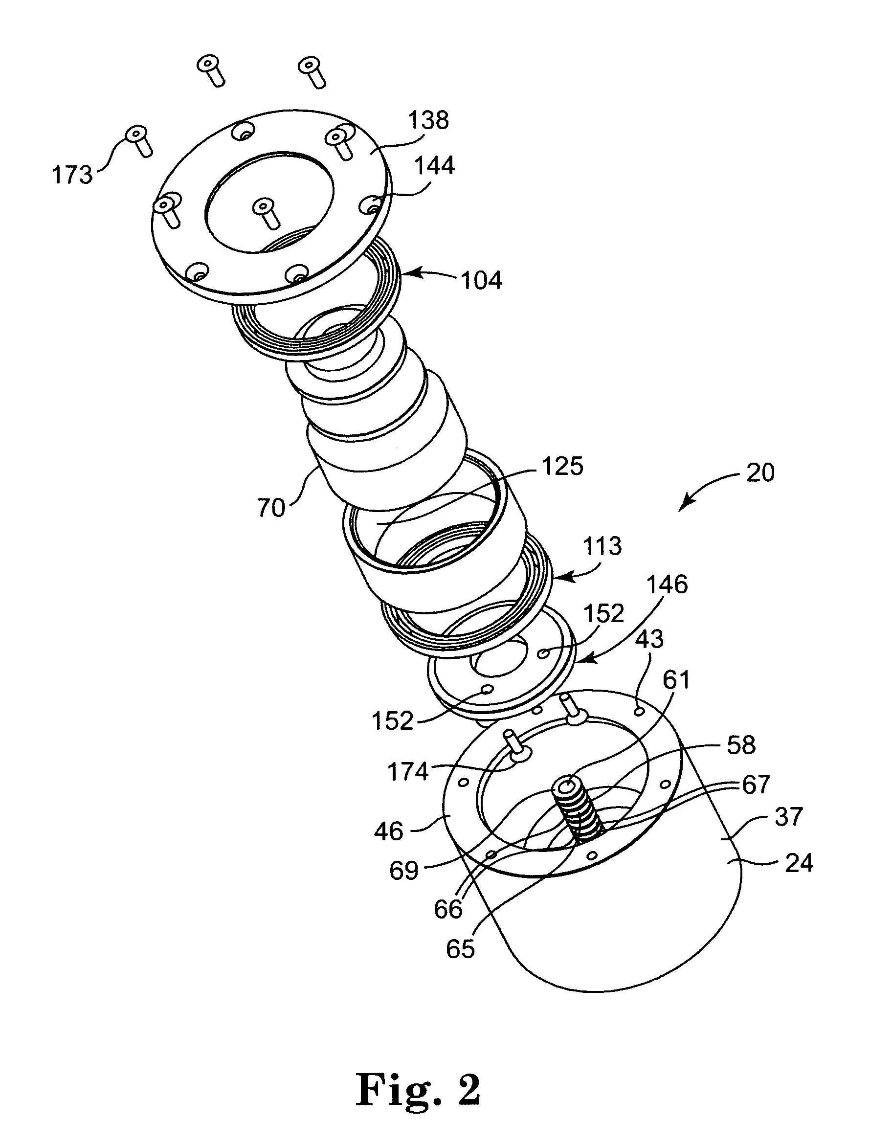
[0027]An exemplary rotary union according to the present invention is described below with reference to FIGS. 1-5. As shown, rotary union 20 includes a cylindrical housing 24, a cylindrical post 58, and a cylindrical rotor 70, which facilitate the transfer of process fluid(s) among locations that rotate relative to one another.

[0028]Housing 24 has a fluid path 31 (e.g., a through-bore) through which a fluid can be conveyed through housing 24. Preferably, housing 24 has a bottom (or base portion) 28. As shown, fluid path 31 extends through bottom 28. Fluid path 31 defines part of a fluid pa...


PUM


Abstract

A rotary union having a housing, a rotor, and a post such that a fluid can be conveyed through the rotary union. The rotor is rotatably coupled to the housing, preferably by at least one bearing interposed between a portion of the rotor exterior and a portion of the housing interior. The post is positioned in the rotary union in a manner effective to help fluidly couple the rotor to the housing and such that an annular gap surrounds at least a portion of the post such that the annular gap constitutes at least a portion of a drain fluid pathway. The present invention also includes fluid delivery systems including such rotary unions and methods of making and / or using such rotary unions.

Description

FIELD OF THE INVENTION[0001]The field of this invention relates to fluid delivery systems, and more particularly, this invention relates to rotary unions, such as may be used to facilitate the transfer of a fluid, typically a liquid, from a first environment, e.g., a fluid source, to a second environment, e.g., a rotating point of use, that rotates relative to the first environment.BACKGROUND OF THE INVENTION[0002]In general, rotary unions and fluid delivery systems are well known, especially in the semiconductor processing industry. In the semiconductor processing industry, a rotary union is commonly used to facilitate the transfer of process liquid(s) from a first environment to a second environment that rotates relative to the first environment. Most commonly, one or more liquid(s) from a generally stationary supply line are being transferred to a rotating point of use. Exemplary semiconductor process tools that use one or more rotary union(s) include spray process tool systems c...

Claims


Application Information

Patent Timeline
Patent Type & Authority Patents(United States)
IPC IPC(8): F16L27/08
CPCF16L27/0828Y10T137/86268F16L27/08F16L27/00
Inventor BENSON, ARNE C.HANZLIK, EDWARD D.
Owner TEL EPION
Why Eureka
Try Eureka