Finger cutter

Inactive Publication Date: 2008-09-16
KANEFUSA HAMONO KOUGIYOU KK
View PDF27 Cites 6 Cited by
  • Summary
  • Abstract
  • Description
  • Claims
  • Application Information

AI Technical Summary

Benefits of technology

[0006]In the present invention, since the cutting edges proximate of tip ends of the cutting portions that perform cutting of groove bottoms of finger joints are comprised of a steel material exhibiting high hardness, it is possible to restrict progress of wear of cutting edges proximate of tip ends of the cutting portions. On the other hand, while the cutting edges of portions other than those proximate of tip ends of cutting portions exhibit a lower hardness than the cutting edges proximate of tip ends of cutting portions, it is possible to restrict chipping of the cutting portions since they are made of a steel material exhibiting high toughness.
[0007]In this manner, according to the present invention, it is possible to improve the wear resistance through the cutting edges proximate of the tip ends that are comprised of a steel material having a high hardness, and since it is possible to improve the chipping resistance through cutting edges of remaining portions that are formed of a steel material exhibiting a higher toughness than the cutting edges proximate of tip ends, it is possible to provide a finger joint cutter having cutting portions that exhibit both, suitable wear resistance and chipping resistance. Moreover, according to the present invention, usage of a material for the tip end cutting portions that includes high-valent elements and that exhibits wear resistance can be minimized.
[0008]The finger joint cutter of the present invention may be arranged in that the steel mat

Problems solved by technology

The wear of cutting edges near the tip ends of the cutting portions that cut the groove bottoms of finger joints will be particularly large.
Where the progress of wear of cutting edges near the tip ends of the cutting portions is fast, the progress of wear of the cutting edges at portions on a base side that continue into the worn tip ends of the cutting edges will become fast, and the life of the cutting portions will become short.
However, by forming

Method used


Image

  • Finger cutter
  • Finger cutter
  • Finger cutter

Examples


Embodiment Construction

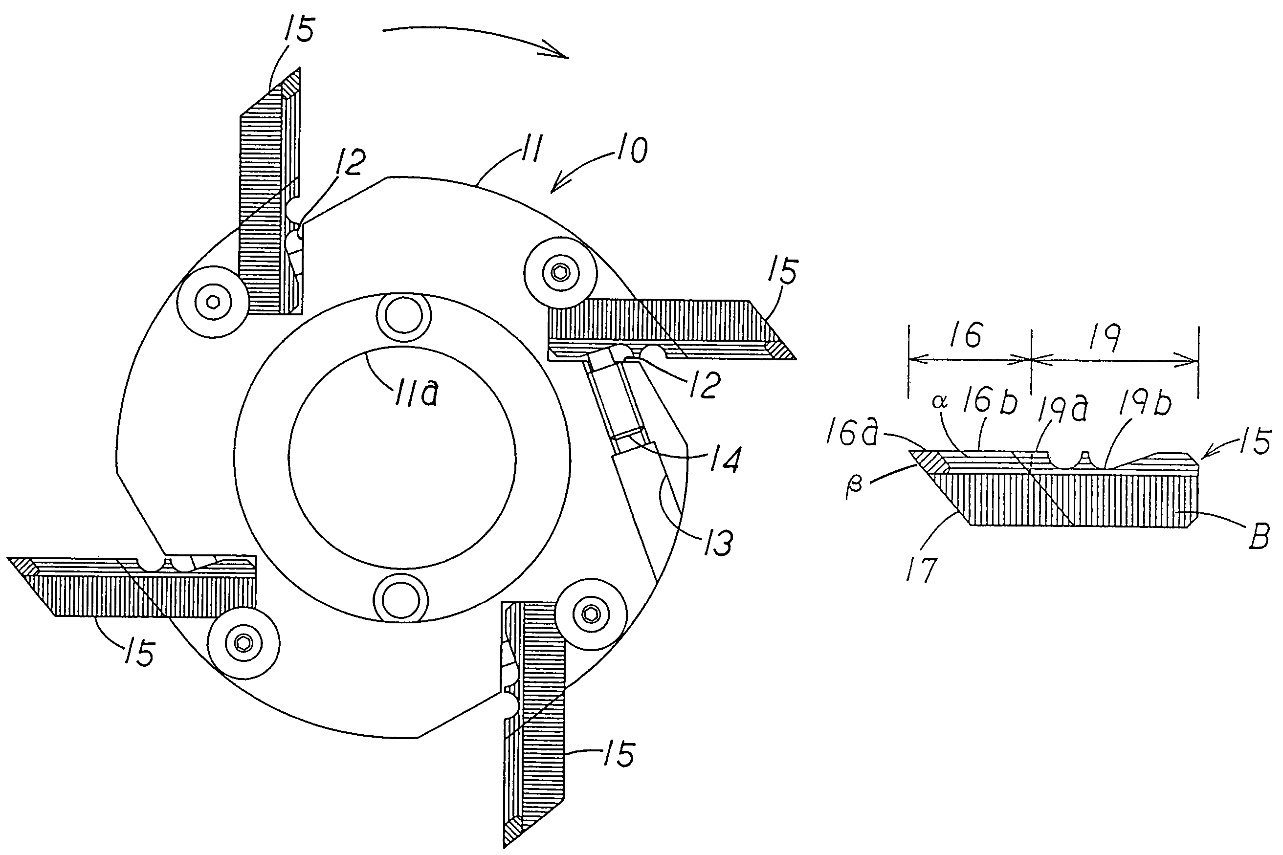
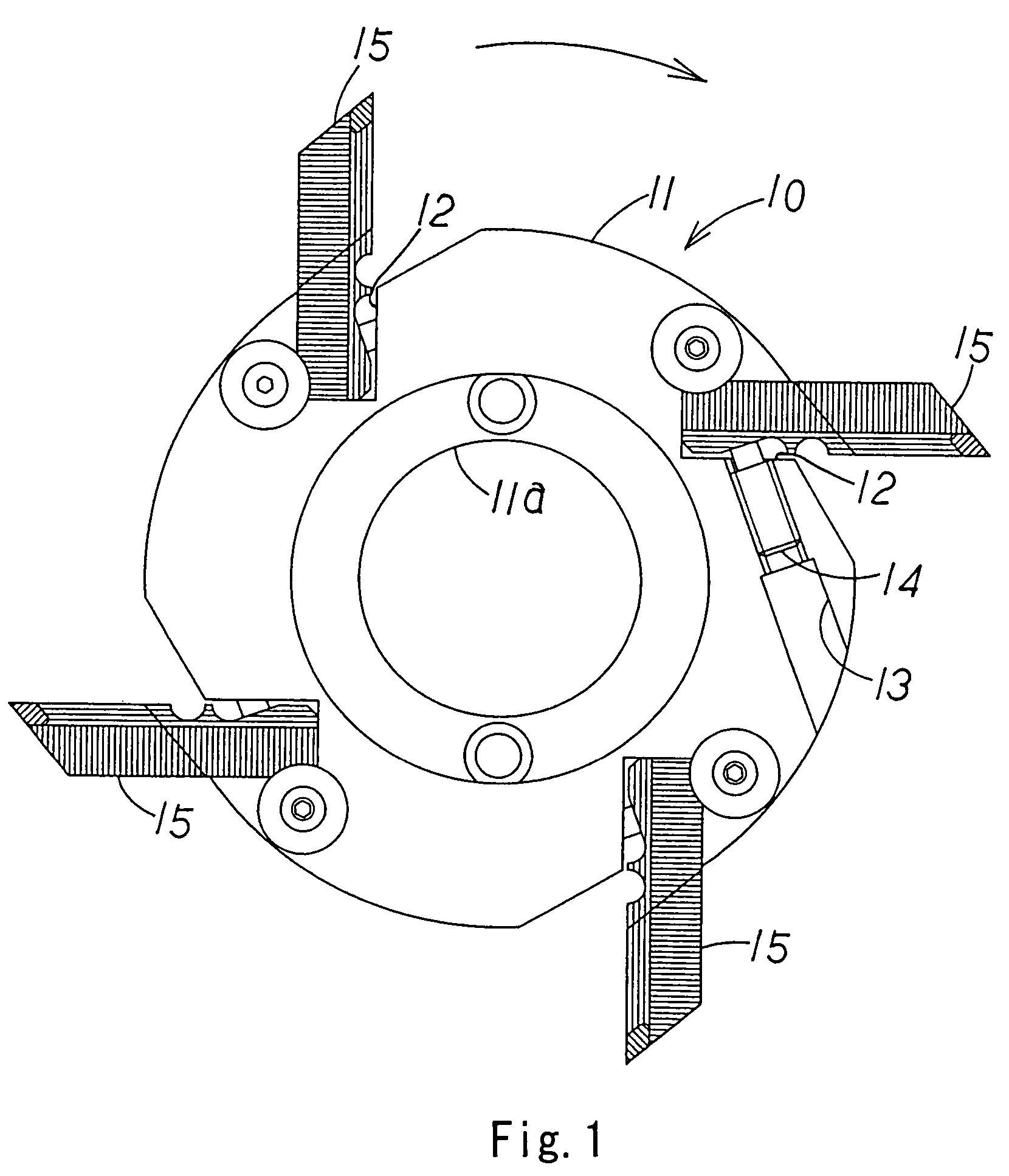
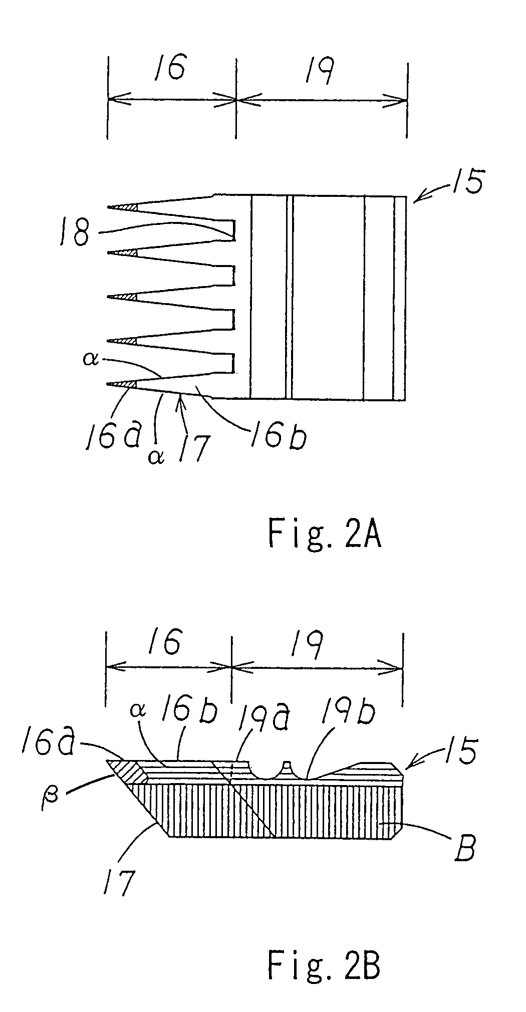
[0016]One embodiment of the present invention will now be explained on the basis of the drawings. FIG. 1 illustrates a replaceable blade type finger joint cutter according to the present invention through a side view. FIGS. 2-A and 2-B illustrate a replaceable blade 15 through a front view and a side view.

[0017]A finger joint cutter 10 is formed with a cylindrical shaped body 11 that is made of steel and is formed with a central hole 11a for inserting a main shaft in its center, and mounting seats 12 extending in axial directions are provided at four portions in a peripheral direction of a peripheral wall of the body 11. Each mounting seat 12 is a concave portion that is inclined frontward in a rotating direction with respect to a radial direction at an angle of approximately 30° and that is notched in a substantially rectangular shape. Replaceable blades 15 are inserted and fitted into the mounting seats 12. Mounting holes 13 are formed on an outer periphery of the body 11 that com...


PUM

PropertyMeasurementUnit
Fractionaaaaaaaaaa
Fractionaaaaaaaaaa
Fractionaaaaaaaaaa

Abstract

Cutting portion regions of replaceable blades that extrude outward in a radial direction at a plurality of portions in a peripheral direction of an outer periphery of a body of a finger joint cutter are arranged in that, as for a cutting portion material that comprises cutting edge, tip end cutting portions are formed of a steel material of high hardness and base portion side cutting portions, which are the remaining portions, are formed of a steel material that exhibits a higher toughness than that of the tip end cutting portions. It is possible to improve the wear resistance through the tip end cutting portions and to improve the chipping resistance by the base portion side cutting portions. The steel material of high hardness comprising the tip end cutting portions and the steel material of high toughness comprising the base portion side cutting portions are successively joined through forge welding.

Description

BACKGROUND OF THE INVENTION[0001]The present invention relates to a finger joint cutter, which is a rotating cutting tool for processing finger joints, a kind of joint used with wood materials or the like.[0002]As illustrated in FIG. 5, a finger joint cutter 1 includes a plurality of cutting portions 3 of a chevron wedge-like shape that project outward in a radial direction from a plurality of portions around an outer periphery of a body 2. A wedge-like finger joint F including a plurality of narrow and deep grooves at an end portion of an object M is cut using the cutting portions 3. Since such deep grooves are processed, the degree of wear of cutting edges of the cutting portions 3 of the finger joint cutter 1 will remarkably vary depending on regions of the cutting edges. The wear of cutting edges near the tip ends of the cutting portions that cut the groove bottoms of finger joints will be particularly large. Where the progress of wear of cutting edges near the tip ends of the c...

Claims


Application Information

Patent Timeline
IPC IPC(8): B27C1/00B27C5/00B27G13/00B23P15/28B27F1/16B27G13/14
CPCB23P15/28B27G13/14B27F1/16
Inventor SOGA, KATSUAKITSUCHIYA, ATSUSHI
Owner KANEFUSA HAMONO KOUGIYOU KK
Why Eureka
Try Eureka