
Method of treating subterranean formations with porous particulate materials

a porous particulate and subterranean technology, applied in the field of subterranean formation treatment, can solve the problems of improper placement downhole, formation damage, and/or proppant pack damage, and achieve the effect of improving the overall system performan

Active Publication Date: 2008-09-23
BAKER HUGHES INC
View PDF103 Cites 124 Cited by
  • Summary
  • Abstract
  • Description
  • Claims
  • Application Information

AI Technical Summary

Benefits of technology

[0016]In a preferred mode, the porous particulate composition is a suspension of porous particulates in a carrier fluid. The suspension preferably forms a pack of particulate material that is permeable to fluids produced from the wellbore and substantially prevents or reduces production of formation materials from the formation into the wellbore.
[0019]In a preferred embodiment, the selectively configured porous particulate materials are derived from lightweight and / or substantially neutrally buoyant particles. The application of selected porous material particulates and relatively lightweight and / or substantially neutrally buoyant particulate material as a fracture proppant particulate advantageously provides for substantially improved overall system performance in hydraulic fracturing applications, or in other well treating applications such as sand control.

Problems solved by technology

Gelling agents for proppant carrier fluids may provide a source of proppant pack and / or formation damage, and settling of proppant may interfere with proper placement downhole.
Formation damage may also be caused by gelled carrier fluids used to place particulates downhole for purposes such as for sand control, such as gravel packs, frac packs, and similar materials.
Unfortunately, increasing particle density leads directly to increasing degree of difficulty with proppant transport and a reduced propped fracture volume for equal amounts of the respective proppant, reducing fracture conductivity.
Previous efforts undertaken to employ lower density materials as proppant have generally resulted in failure due to insufficient strength to maintain fracture conductivity at even the lowest of closure stresses (1,000 psi).
Such beads, however, have not been entirely successful primarily due to limitations of the base material.
While PSDVB beads offered excellent deformability and elasticity, they lacked the structural integrity to withstand high closure stresses and temperatures.
As a proppant, natural walnut hulls have very limited applicability, because they deform fairly readily upon application of closure stress.
This deformation drastically reduces conductivity and limits utility of the natural material to relatively low-closure environments.
As density increases, so too does the difficulty of placing that particle evenly throughout the created fracture geometry.
Excessive settling can often lead to bridging of the proppant in the formation before the desired stimulation is achieved.

Method used


Image

  • Method of treating subterranean formations with porous particulate materials
  • Method of treating subterranean formations with porous particulate materials
  • Method of treating subterranean formations with porous particulate materials

Examples


example 1

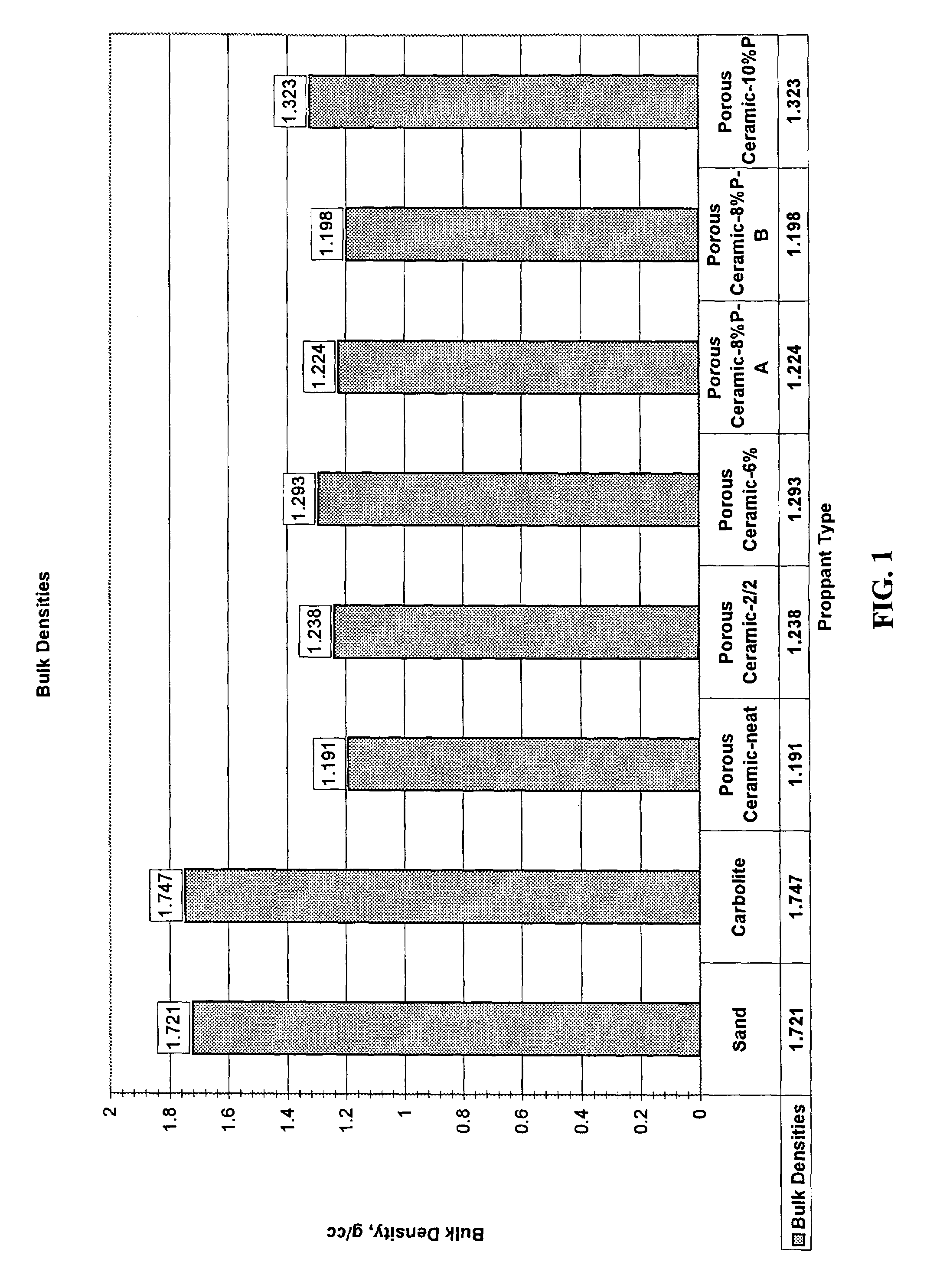
[0119]To obtain the data for this example, the following procedure was followed: Measured mass of 25 ml of sample on a graduate cylinder. Cylinder was tapped several times on the countertop and the volume adjusted to an even 25 ml prior to weighing. Mass / volume=bulk density.

[0120]The data of this example is shown in Table 1:

[0121]

TABLE 1Bulk DensitiesSand1.721CarboLite1.747Porous Ceramic—Neat1.191Porous Ceramic—2 / 21.238Porous Ceramic—6%1.293Porous Ceramic—8% P-A1.224Porous Ceramic—8% P-B1.198Porous Ceramic—10% P1.32 

FIG. 1 illustrates comparisons of the bulk densities of various proppants / sand control materials to samples of a selected porous ceramic material (from Carbo Ceramics, Inc.).

[0122]In the examples, “Carbolite” is a commercial proppant available from Carbo Ceramics, Inc. “Neat” is untreated porous ceramic material from Carbo Ceramics, Inc., “2 / 2” is porous ceramic material from Carbo Ceramics, Inc. treated with 2% by weight of particle epoxy inner coating / penetrating mater...

example 2

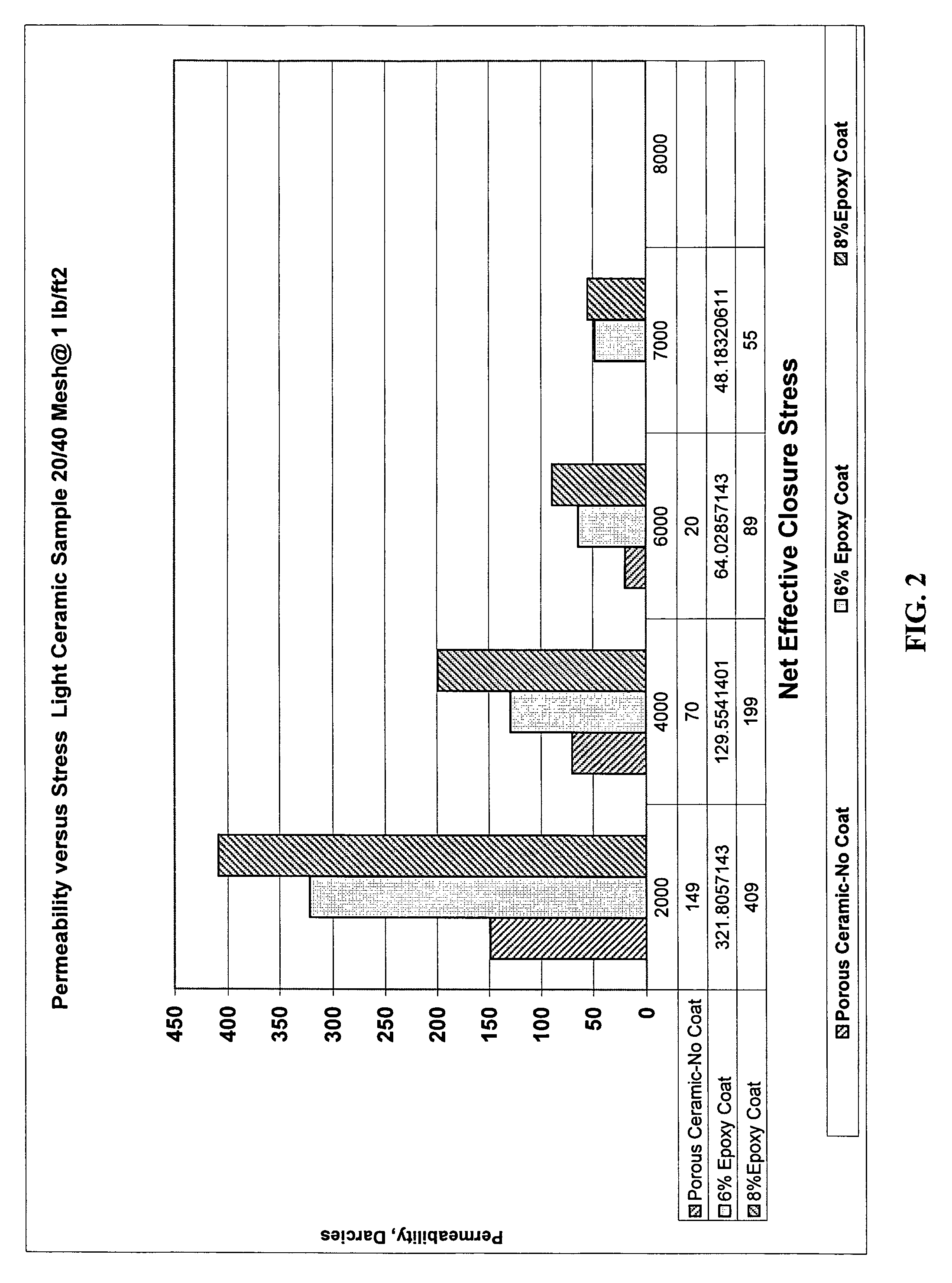
[0125]The porous particulate material employed was from “Carbo Ceramics” having a size of about 20 / 40 mesh. The particulate material was treated with various penetrating / coating materials corresponding to the same epoxy or phenol formaldehyde materials used above. The treated particulate material was tested alone, with no other particulate material blended in. Comparison materials include Jordan Sand, “Econoprop” proppant from Carbo Ceramics, “Econoflex” (coated Econoprop proppant), Hickory sand (Brady Sand), “PR6000” 2% coated Ottawa sand from BORDEN, and “Carbolite” proppant from Carbo Ceramics.

[0126]Conductivity tests were performed according to API RP 61 (1st Revision, Oct. 1, 1989) using an API conductivity cell with Ohio sandstone wafer side inserts. Each particulate material sample was loaded into the cell and closure stress applied to the particulate material using a “DAKE” hydraulic press having a “ROSEMOUNT” differential transducer (#3051C) and controlled by a “CAMILE” con...

example 3

[0131]Using the selected treated material of the Examples above, particles may be produced that are capable for use, such as having sufficient crush resistance for use or do not crush, under conditions of 2000 psi closure stress or greater, alternatively 2500 psi closure stress or greater, alternatively 3000 psi closure stress or greater, alternatively up to at least about 6000 psi closure stress, alternatively up to at least about 7000 psi closure stress, and alternatively at least about 8000 psi closure stress, i.e., almost as resistant to crush as commercial ceramic proppants which are heavier (e.g., commercial ceramic proppant (CarboLite) is about 40% heavier). In another embodiment, particles may be produced that are capable for use (e.g., have sufficient crush resistance for use or do not crush) under conditions of from about 2000 psi closure stress to about 8000 psi closure stress, alternatively from about 2500 psi closure stress to about 8000 psi closure stress, alternativel...


PUM


Abstract

Methods and compositions useful for subterranean formation treatments, such as hydraulic fracturing treatments and sand control that include porous materials. Such porous materials may be selectively configured porous material particles manufactured and / or treated with selected glazing materials, coating materials and / or penetrating materials to have desired strength and / or apparent density to fit particular downhole conditions for well treating such as hydraulic fracturing treatments and sand control treatments. Porous materials may also be employed in selected combinations to optimize fracture or sand control performance, and / or may be employed as relatively lightweight materials in liquid carbon dioxide-based well treatment systems.

Description

SPECIFICATION[0001]This application claims priority to provisional application serial No. 60 / 407,734, filed on Sep. 3, 2002 and provisional application Ser. No. 60 / 428,836, filed on Nov. 25, 2002.FIELD OF THE INVENTION[0002]This invention relates generally to methods and compositions useful for subterranean formation treatments, such as hydraulic fracturing treatments and sand control.BACKGROUND OF THE INVENTION[0003]Hydraulic fracturing is a common stimulation technique used to enhance production of fluids from subterranean formations. In a typical hydraulic fracturing treatment, fracturing treatment fluid containing a solid proppant material is injected into the formation at a pressure sufficiently high enough to cause the formation or enlargement of fractures in the reservoir. During a typical fracturing treatment, proppant material is deposited in a fracture, where it remains after the treatment is completed. After deposition, the proppant material serves to hold the fracture op...

Claims


Application Information

Patent Timeline
IPC IPC(8): E21B43/267E21B43/02C09K8/80
CPCC09K8/805E21B43/267Y10T428/2998Y10T428/2993Y10T428/2996Y10T428/2982Y10T428/2991Y10T428/2995
Inventor STEPHENSON, CHRISTOPHER JOHNRICKARDS, ALLAN RAYBRANNON, HAROLD DEANGUPTA, D. V. SATYANARAYANA
Owner BAKER HUGHES INC
Learn More