Doherty amplifier with improved linearity

Inactive Publication Date: 2008-09-23
KOKUSA ELECTRIC CO LTD
View PDF5 Cites 73 Cited by
  • Summary
  • Abstract
  • Description
  • Claims
  • Application Information

AI Technical Summary

Benefits of technology

[0021]It is an object of the invention to provide a highly effici

Problems solved by technology

There are limits to reducing the power consumption of the common amplifier only using a feedforward distortion compensator or pre-distortion compensator.
Actually, however, a gain increase of as much as 3 dB cannot be expected since the load of the carrier amplifier varies.
As described above, where the convention

Method used


Image

  • Doherty amplifier with improved linearity
  • Doherty amplifier with improved linearity
  • Doherty amplifier with improved linearity

Examples


first embodiment

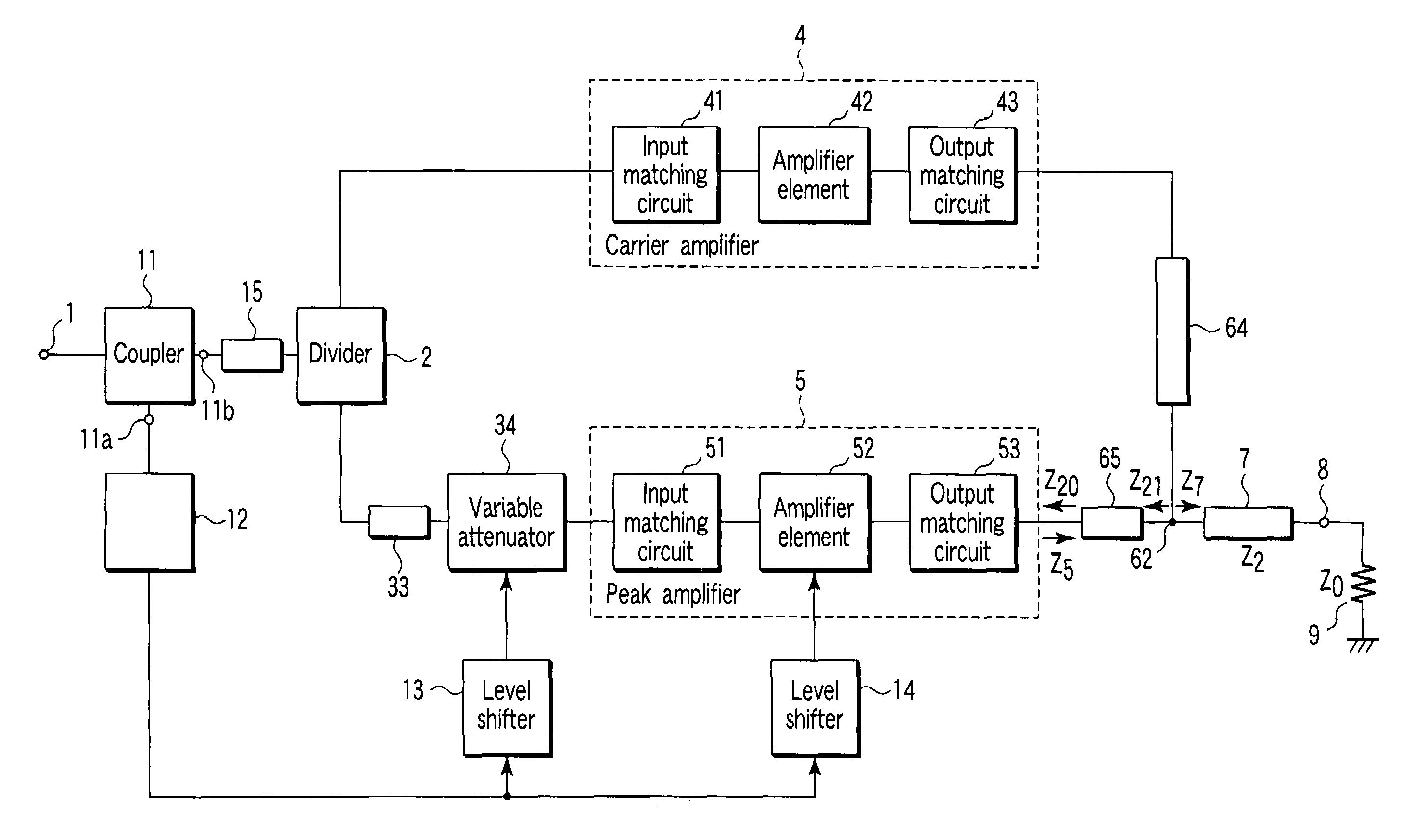
[0037]Referring to FIG. 4, in an amplifier apparatus according to a first embodiment of the invention, an input signal from a signal input terminal 1 is input to a coupler 11. The coupler 11 is, for example, a T-branch line formed on a wiring substrate, a 3-dB coupler or an unequal divider, and includes a first coupling terminal 11a and second coupling terminal 11b. The first coupling terminal 11a is connected to the input terminal of a level sensor 12, and the second coupling terminal 11b is connected to the input terminal of a delay line 15. The level sensor 12 is, for example, a wave detector. The output terminal of the delay line 15 is connected to the input terminal of a divider 2.

[0038]One output terminal of the divider 2 is connected to the input terminal of a carrier amplifier 4 that comprises an input matching circuit 41, amplifier element 42 and output matching circuit 43. The other output terminal of the divider 2 is connected to the input terminal of a variable attenuato...

second embodiment

[0063]Referring to FIG. 6, an amplifier apparatus according to a second embodiment will be described. As shown in FIG. 6, the amplifier apparatus of the second embodiment is acquired by adding, to the apparatus of the first embodiment, a level shifter 16 provided between the level sensor 12 and preamplifier 54, a preamplifier 44 that is provided at the input side of the carrier amplifier 4 and operates as a class AB amplifier, and a preamplifier 54 provided at the input side of the peak amplifier 5. The signal sensed by the level sensor 12 is converted into a bias voltage by the level shifter 16, and input to the control terminal of the preamplifier 54. The bias voltage controls the preamplifier 54 to shift from class C to class AB. The other elements of the second embodiment are similar to those of the first embodiment. They are denoted by corresponding reference numerals, and are not described in detail.

[0064]The level shifter 16 performs bias control on the preamplifier 54 to shi...

third embodiment

[0067]Referring then to FIG. 7, an amplifier apparatus according to a third embodiment will be described.

[0068]As shown in FIG. 7, the third embodiment is acquired by inserting a variable attenuator 21 and a preamplifier 22, which operates as a class AB amplifier, between the delay line 15 and divider 2 of the first embodiment. Further, the signal sensed by the level sensor 12 is converted into a control voltage by the level shifter 13 and then input to the variable attenuator 21. Furthermore, the third embodiment employs no element corresponding to the variable attenuator 34 in the first embodiment. Since the other elements of the third embodiment are similar to those of the first embodiment, they are denoted by corresponding reference numerals, and are not described in detail.

[0069]The signal input to the input terminal 1 is guided to the coupler 11. From the coupler 11, signals are output to the first and second coupling terminals 11a and 11b. The signal output from the second co...


PUM


Abstract

A first control unit controls a bias applied to the peak amplifier to (a) make a peak amplifier operate as class C when the level of the input signal is lower than a first threshold value, to (b) make the peak amplifier operate as class AB with a second conduction angle substantially equal to a first conduction angle, when the level of the input signal is higher than a second threshold value higher than the first threshold value, and to (c) make the peak amplifier operate as class AB with a third conduction angle smaller than the first conduction angle, when the level of the input signal is not less than the first threshold value and not more than the second threshold value.

Description

CROSS-REFERENCE TO RELATED APPLICATIONS[0001]This application is based upon and claims the benefit of priority from prior Japanese Patent Application No. 2005-303093, filed Oct. 18, 2005, the entire contents of which are incorporated herein by reference.BACKGROUND OF THE INVENTION[0002]1. Field of the Invention[0003]The present invention relates to a linearity-improved Doherty amplifier apparatus.[0004]2. Description of the Related Art[0005]In conventional common amplifiers for amplifying the power of a radio frequency signal, such as a code division multiple access (CDMA) signal or multi-carrier signal, the operation range is widened to the region near the saturation region, using a distortion compensator, thereby reducing the power consumption. There are limits to reducing the power consumption of the common amplifier only using a feedforward distortion compensator or pre-distortion compensator. In recent years, attention has been paid to Doherty amplifiers as highly efficient amp...

Claims


Application Information

Patent Timeline
IPC IPC(8): H03F3/68
CPCH03F3/602H03F1/0288
Inventor OKUBO, YOICHITAKEDA, YASUHIRONAKAMURA, MANABUHONGO, NAOKIADACHI, MASARU
Owner KOKUSA ELECTRIC CO LTD
Why Eureka
Try Eureka