
Multispectral, multifusion, laser-polarimetric optical imaging system

a laser-polarimetric and optical imaging technology, applied in the field of optical imaging systems, can solve the problems of inability to analyze the depolarization of circularly-polarized light, inability to provide a desirable contrast between the target and the background noise of interfering hardware-based super-resolution approaches, and inability to achieve the effect of maximizing the contrast of images captured

Inactive Publication Date: 2008-09-23
THE UNIVERSITY OF AKRON
View PDF12 Cites 25 Cited by
  • Summary
  • Abstract
  • Description
  • Claims
  • Application Information

AI Technical Summary

Benefits of technology

The system achieves improved image contrast and specificity, capable of analyzing circularly-polarized light and providing enhanced imaging in various applications, including homeland security, medical, and industrial uses, with reduced noise and improved performance in adverse conditions.

Problems solved by technology

However, linear-polarized light tends to lose a significant degree of polarization in a large number of light-scattering media.
Such attempts have failed to analyze the depolarization of circularly-polarized light, based on the Mueller-matrix concept, by detecting highly-scattered light from biologically-inspired phantoms as well as, to a lesser extent, from biological tissues.
But again, this hardware-based super-resolution approach does not provide a desirable contrast between the target and interfering background noise.
However, none of these studies have fused dual-energy capabilities with polarimetric measurements.
But since the polarimeters involved in these studies are incomplete, they do not take into account elliptical polarization states.
And again, these studies do not contemplate the fusion of dual-energy techniques with polarimetric imaging principles.
Finally, the exploitation of polarization principles fused with dual-energy capabilities has been proposed, but such proposals have all neglected to incorporate the means of dual-rotating retarder complete polarimeter.

Method used


Image

  • Multispectral, multifusion, laser-polarimetric optical imaging system
  • Multispectral, multifusion, laser-polarimetric optical imaging system
  • Multispectral, multifusion, laser-polarimetric optical imaging system

Examples


Embodiment Construction

[0020]Certain terminology is used herein for convenience only and is not to be taken as a limitation on the present invention. Further, in the drawings, certain features may be shown in somewhat schematic form.

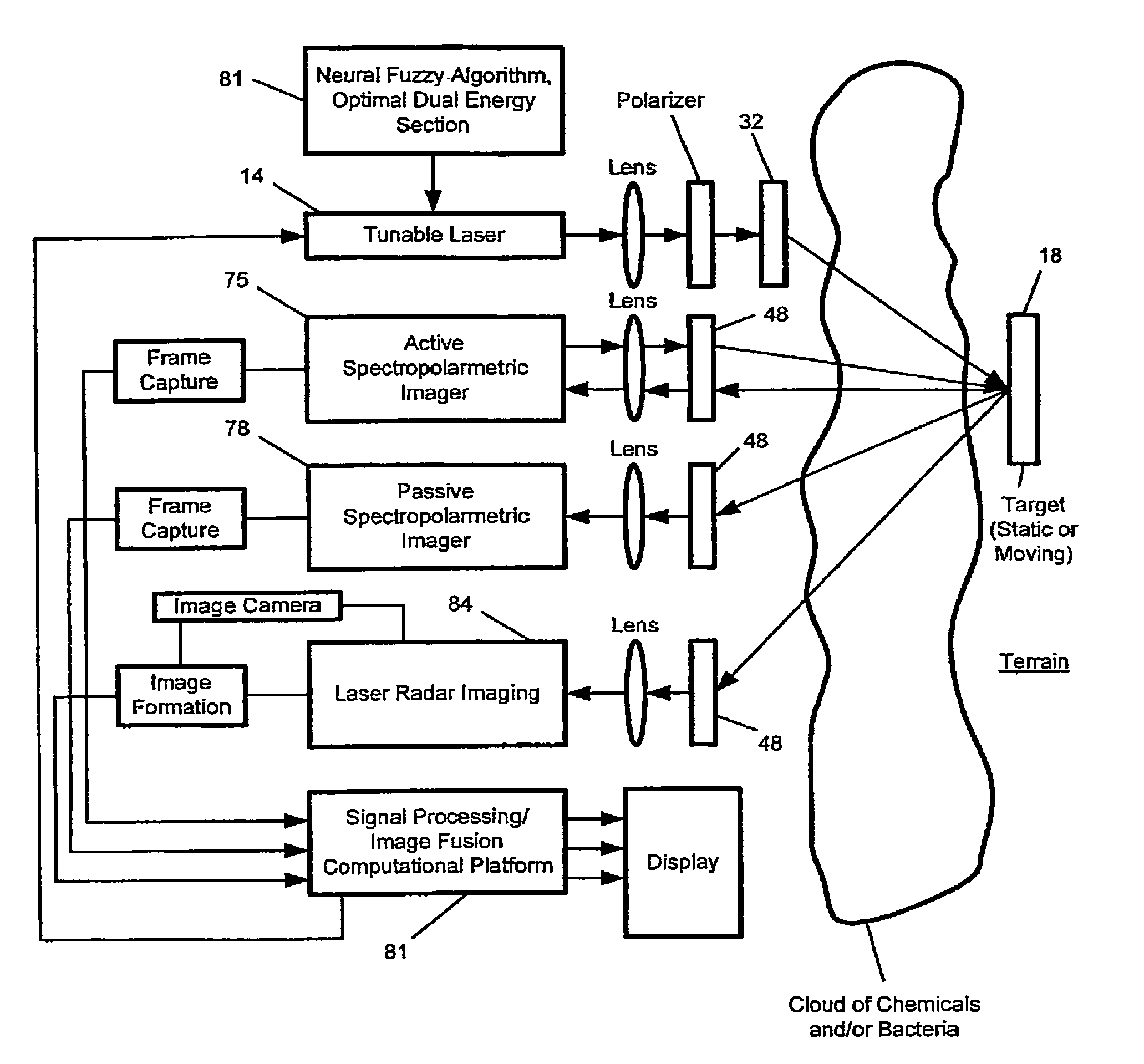
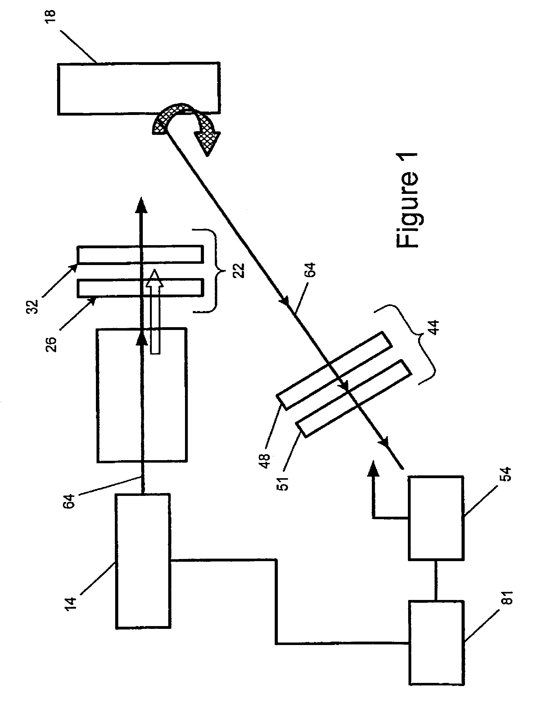
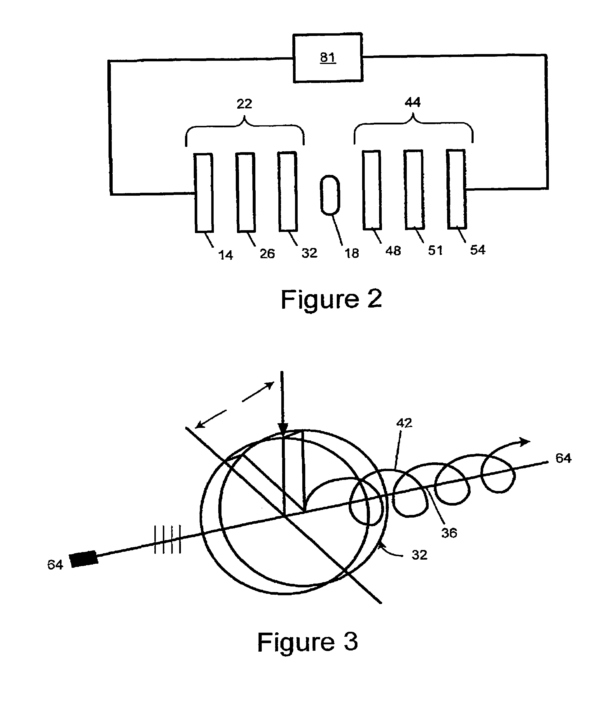
[0021]FIG. 1 illustrates one embodiment of a multi-energy polarization imaging system 10 according to the present invention. The imaging system 10 includes a light source 14 for illuminating a target 18 with a first quantity of light having a first wavelength and a second quantity of light having a second wavelength. The second wavelength is different than the first wavelength to produce a high-contrast image. A polarization-state generator 22 is provided for generating a polarization 22 state for each of the first and second quantities of light. The polarization-state generator includes a first polarizer 26 through which the first and second quantities of light are transmitted before entering a first waveplate 32, which creates a phase difference between an ordinary component...


PUM

PropertyMeasurementUnit
reflectanceaaaaaaaaaa
wavelengthaaaaaaaaaa

Abstract

In one embodiment, the present invention is directed to a multi-energy polarization imaging method consisting of a multi-fusion, dual-rotating retarder / multiple-energy complete Mueller matrix-based polarimeter and dual-energy capabilities. By subtracting polarimetric parameters such as degree of polarization, degree of linear polarization, degree of circular polarization, respectively, obtained with interrogation light beams of wavelengths λ1, and λ2, the system of the present invention can obtain, in one embodiment, enhanced imaging.

Description

RELATED APPLICATIONS[0001]This application claims the benefit of U.S. Provisional Application No. 60 / 482,386, filed Jun. 25, 2003.FIELD OF THE INVENTION[0002]The invention relates generally to optical-imaging systems, and more particularly to a multi-fusion, dual-rotating retarder / multiple-energy complete Mueller matrix-based polarimeter. The proposed imaging system is based on multi-wavelength laser-polarimetric interrogation of targets surrounded by scattered media or any media in general, using the Mueller matrices formalism together with dual-energy subtraction techniques. Specifically, the term multifusion describes the use of several imaging functions altogether such as polarimetric imaging, dual-energy subtraction, multifocal imaging, multiple-exposures, and other. By subtracting polarimetric parameters such as degree of polarization (DOP), degree of linear polarization (DOLP), degree of circular polarization, respectively (DCP), obtained with interrogation light beams of wav...

Claims


Application Information

Patent Timeline
Patent Type & Authority Patents(United States)
IPC IPC(8): G01J4/00G01JG01J3/02G01J3/28G01J3/36G01J4/04G01N21/21
CPCG01J3/02G01J3/021G01J3/0224G01J3/2823G01N21/21G01J3/433G01J3/447G01J4/04G01J3/36
Inventor GIAKOS, GEORGE C.
Owner THE UNIVERSITY OF AKRON
Learn More