Nonvolatile programmable logic circuit

a programmable logic and non-volatile technology, applied in the field of program registers, can solve the problem of leaking of various information stored in latches in power-off mode, and achieve the effect of reducing power consumption

Active Publication Date: 2008-09-23
SK HYNIX INC
View PDF15 Cites 9 Cited by
  • Summary
  • Abstract
  • Description
  • Claims
  • Application Information

AI Technical Summary

Benefits of technology

[0009]Accordingly, it is an object of the present invention to provide a nonvolatile programmable logic circuit using

Problems solved by technology

However, since a SRAM (Static Random Access Memory) is used as the conventional programmable

Method used


Image

  • Nonvolatile programmable logic circuit
  • Nonvolatile programmable logic circuit
  • Nonvolatile programmable logic circuit

Examples


Embodiment Construction

[0043]The present invention will be described in detail with reference to the accompanying drawings.

[0044]A nonvolatile ferroelectric programmable logic circuit according to an embodiment of the present invention can be applied to various logic circuits such as a CAM (Content Addressable Memory), a CAM array, a buffer, a buffer array, an inversion means, a switch, a transmission switch, a pull-up / pull-down switch, a look-up table, a latch and a flip-flop.

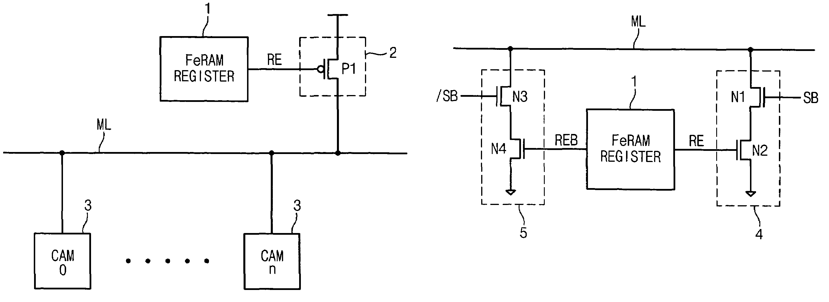
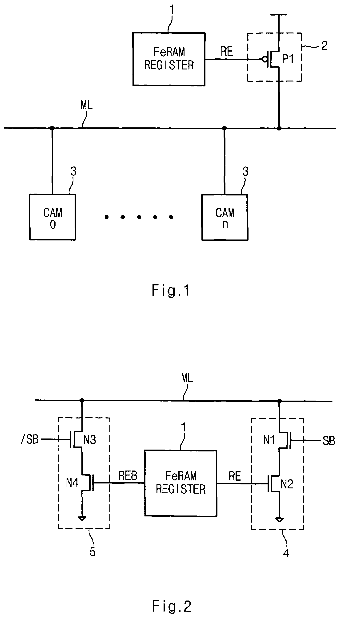
[0045]FIG. 1 is a block diagram illustrating a FeRAM register 1 applied to a pull-up operation of a match line connected to a plurality of CAMs according to an embodiment of the present invention.

[0046]In an embodiment, the nonvolatile programmable logic circuit comprises a FeRAM register 1, a pull-up switch 2 and a plurality of CAMs 3.

[0047]The plurality of CAMs 3 each connected to match lines ML constitute an array.

[0048]The FeRAM register 1 outputs a control signal RE to selectively control a switching operation of the pull-up sw...


PUM


Abstract

A nonvolatile programmable logic circuit using a ferroelectric memory performs a nonvolatile memory function and an operation function without additional memory devices, thereby reducing power consumption. Also, a nonvolatile ferroelectric memory is applied to a FPGA (Field Programmable Gate Array), thereby preventing leakage of internal data and reducing the area of a chip.

Description

CROSS-REFERENCES TO RELATED APPLICATIONS[0001]The present application claims priority to Korean patent application number 10-2003-0020767, filed on Apr. 2, 2003 and Korean patent application number 10-1999-0049972 (now U.S. Pat. No. 6,363,004). granted filing date Mar. 26, 2002, which is incorporated by reference in its entirety.BACKGROUND OF THE INVENTION[0002]1. Field of the Invention[0003]The present invention generally relates to a program register using a nonvolatile memory device and a programmable logic circuit using the same, and more specifically, to a technology for storing data or performing an operation on the data without additional memory devices, thereby reducing the area of the circuit.[0004]2. Description of the Prior Art[0005]Generally, a ferroelectric random access memory (hereinafter, referred to as ‘FRAM’) has attracted considerable attention as next generation memory device because it has a data processing speed as fast as a Dynamic Random Access Memory DRAM an...

Claims


Application Information

Patent Timeline
IPC IPC(8): G11C15/00G11C11/22G11C7/06H03K19/20G11C15/04H03K19/173H03K19/185
CPCG11C15/046G11C11/22
Inventor KANG, HEE BOK
Owner SK HYNIX INC
Why Eureka
Try Eureka