Radio frequency identification (RFID) and programmable logic device (PLD) integration and applications

a technology of programmable logic devices and radio frequency identification, applied in the direction of electrical signalling details, instruments, burglar alarm mechanical actuation, etc., can solve the problems of battery powering the bram storing encryption software running out of power, device small, and inoperable pld

Active Publication Date: 2008-09-30
XILINX INC
View PDF9 Cites 19 Cited by
  • Summary
  • Abstract
  • Description
  • Claims
  • Application Information

AI Technical Summary

Benefits of technology

[0018]According to embodiments of the present invention, components of an RFID tag are connected to a PLD to provide power to components of the PLD for operation. The RFID antenna can be: (1) formed in layers of the die where the PLD is formed, (2) formed on or provided in a chip carrier or die package containing the PLD die, or (3) provided on a PCB containing the PLD chip with the antenna connecting to an input / output port of the PLD for communications. Power provided through the RFID interface in some embodiments can limit battery power consumption to assure critical code stored in BRAM is not lost while the PLD is unpowered in storage. The RFID components can further provide an interface for programming of the PLD and read back of its content to verify programming and other parameters. The RFID interface to the PLD can further provide for identification of the PLD for inventory control as well as secure access to the PLD. The RFID interface to a PLD may also provide enough energy to completely power the PLD, thus not requiring the need for other power sources in normal and other modes of operation.

Problems solved by technology

Lack of its own power supply makes the device quite small.
The complexity and size of the PLD has in the past prevented its use with an RFID tag.
With PLDs shipped in a container or stored for long periods of time, one concern is that the batteries powering the BRAM storing encryption software will run out of power rendering the PLD inoperable.

Method used


Image

  • Radio frequency identification (RFID) and programmable logic device (PLD) integration and applications
  • Radio frequency identification (RFID) and programmable logic device (PLD) integration and applications
  • Radio frequency identification (RFID) and programmable logic device (PLD) integration and applications

Examples


Embodiment Construction

[0030]FIGS. 4-6 illustrate how components of an RFID tag can be combined with a PLD, such as a CPLD or an FPGA. The passive tag needs an antenna and simple circuit to communicate. FIG. 4 illustrates how the RFID tag antenna 40 can be formed in one or more metal layers 42 and 44 of the semiconductor die where the PLD is formed. The antenna 40 loops are interconnected with vias to, for example, n-doped areas in a p substrate, and further are connected to an electrical connection to provide signals to internal components of the PLD.

[0031]FIG. 5 illustrates how the antenna 50 can be provided on a chip carrier or die package 52 containing the PLD die 54. The antenna 50 can be wire bonded to leads of the PLD die 54 to electrically connect to internal components of the PLD. The antenna 50 can be formed on the lid 56 of the package 52, or formed separate from the chip carrier and attached to the PLD die 54 inside the package 52.

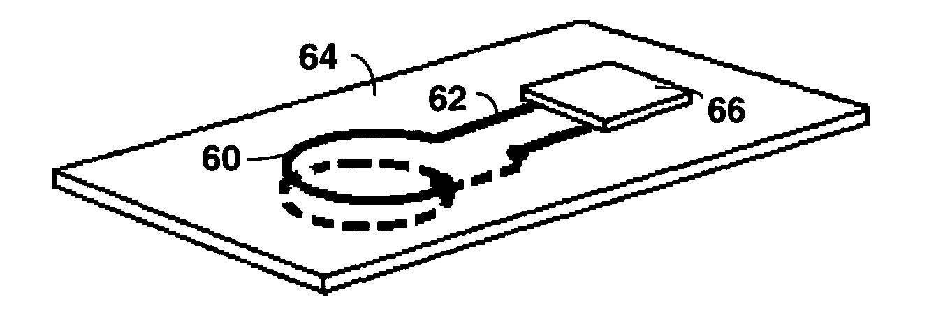
[0032]FIG. 6 further illustrates how the RFID antenna 60 can be...


PUM


Abstract

A Programmable Logic Device (PLD), such as a Field Programmable Gate Array (FPGA), is provided with components of a Radio Frequency Identification (RFID) tag and circuitry to enhance operation. The RFID antenna and circuitry is provided in either directly in layers of the die forming the PLD, on a die package containing the PLD die, or on a printed circuit board containing the PLD. An RFID antenna provides a source of power from an external electromagnetic radiation source (such as an RFID reader) during storage of the PLD to prevent loss of decryption software in volatile memory should batteries run down. The RFID antenna can further provide a path for providing a bitstream to program the PLD as well as to read data to verify programming. With multiple PLDs having RFID antennas, programming of the PLDs can be performed in parallel. Further, the RFID antenna can be used with limited PLD resources to identify the PLD for inventory.

Description

BACKGROUND[0001]1. Technical Field[0002]The present invention relates to a Radio Frequency Identification (RFID) tag circuitry and antenna used in combination with a Programmable Logic Device (PLD).[0003]2. Related Art[0004]Radio Frequency Identification (RFID) is a method of remotely storing and retrieving data and identification using devices called RFID tags (or RFID transponders). RFID tags contain antennas to enable them to receive and respond to radio-frequency queries from an RFID transceiver. An RFID tag can be attached to or incorporated into a product, such as by placing the RFID tag in an adhesive sticker attached to the product.[0005]FIG. 1 shows an RFID reader antenna 2 and a tag antenna 4, illustrating use of a loop antenna used to form both the RFID tag and the RFID reader. As illustrated, the antennas 2 and 4 operate similar to a transformer to magnetically couple the antennas when one of the loops, in the case of the reader antenna 2, is energized with an alternatin...

Claims


Application Information

Patent Timeline
Patent Type & Authority Patents(United States)
IPC IPC(8): G08B13/14
CPCG06K19/07758G06K19/07749
Inventor DRIMER, SAAR
Owner XILINX INC
Why Eureka
Try Eureka