Cutting equipment for continuous form

a technology of cutting equipment and continuous form, which is applied in the direction of metal working apparatus, web handling, article delivery, etc., can solve the problems of limited system general productivity results, affecting the productivity of automatic processing of documents using these equipments, and limiting the obtainable cutting speed. , to achieve the effect of high productivity, reliable results, and limited cos

Inactive Publication Date: 2008-10-07
TECNAU
View PDF25 Cites 25 Cited by
  • Summary
  • Abstract
  • Description
  • Claims
  • Application Information

AI Technical Summary

Benefits of technology

[0017]The principal object of the present invention is to accomplish a cutting equipment for continuous forms that ensures a high productivity and which results reliable, noiseless and of limited cost.
[0020]Another object of the invention is to achieve a cutting equipments of high reliability and of low time of adherence of the cut portion of the form with the moving blade.
[0022]Still another object of the invention it is to realize a cutting equipment for continuous forms that allows easy maintenance operations of the cutting mechanism.
[0025]A further object of the invention is to accomplish an intermittent motion transversal cutting equipment of high reliability, in which the form is introduced at substantially constant velocity and in which the loop section upstream of the cutting feeding device results stable and of limited dimensions.
[0026]In accomplishing this and other objects there is provided a cutting equipment for continuous forms including an input moving device, a loop forming device, a cutting feeding device and a transversal cutting mechanism and means for setting data of the form to be cut, said equipment further comprising: an input servomechanism for said input moving device including an input position encoder for the entering of said form; a loop forming device including at least a loop sensor; a feeding servomechanism of the cutting feeding device including an intermediate position encoder, said feeding servomechanism moving the section of form to be cut in response to said setting data and to signals of said intermediate position encoder; and a cutting servomechanism of the transversal cutting mechanism including a cutting position encoder. Said cutting servomechanism is servoized to said cutting position encoder and the servomechanism of said cutting mechanism is servoized to said intermediate position encoder; said input servo-mechanism being servoized to said feeding encoder and to said at least one loop sensor for minimizing the variation of the velocity of the entering form.

Problems solved by technology

Despite it and in dependence on the interruptions, the general productivity of the system results limited by the times of cutting.
The velocity of the forms can be sufficiently high in cutting equipments having helicoidal rotating blades with cutting on the fly and the use of these equipments in the systems of automatic processing of documents is not penalizing.
Nevertheless these equipments result particularly expensive in the purchase and in the maintenance.
The cutting equipments which operate while the form is at rest are much less expensive than the cutting equipments operating on the fly but, still today, the obtainable cutting velocity represents a limit to the productivity of the automatic processing of documents using these equipments.
In particular, also the above known equipment has problems in transmitting the start and stop commands to the section of form to be cut.
Another problem of the cutting equipments operating while the form is at rest arises from the fact that the formation of the loops is a source of notable noise and instability with risks of tears in the web and errors in the cuts.
Also in this device the length of the entering form and the length of the loop section are subjected to accelerations and brakes with tensions on the incoming form, risks of slippage and limitations on the obtainable cutting speed.

Method used


Image

  • Cutting equipment for continuous form
  • Cutting equipment for continuous form
  • Cutting equipment for continuous form

Examples


Embodiment Construction

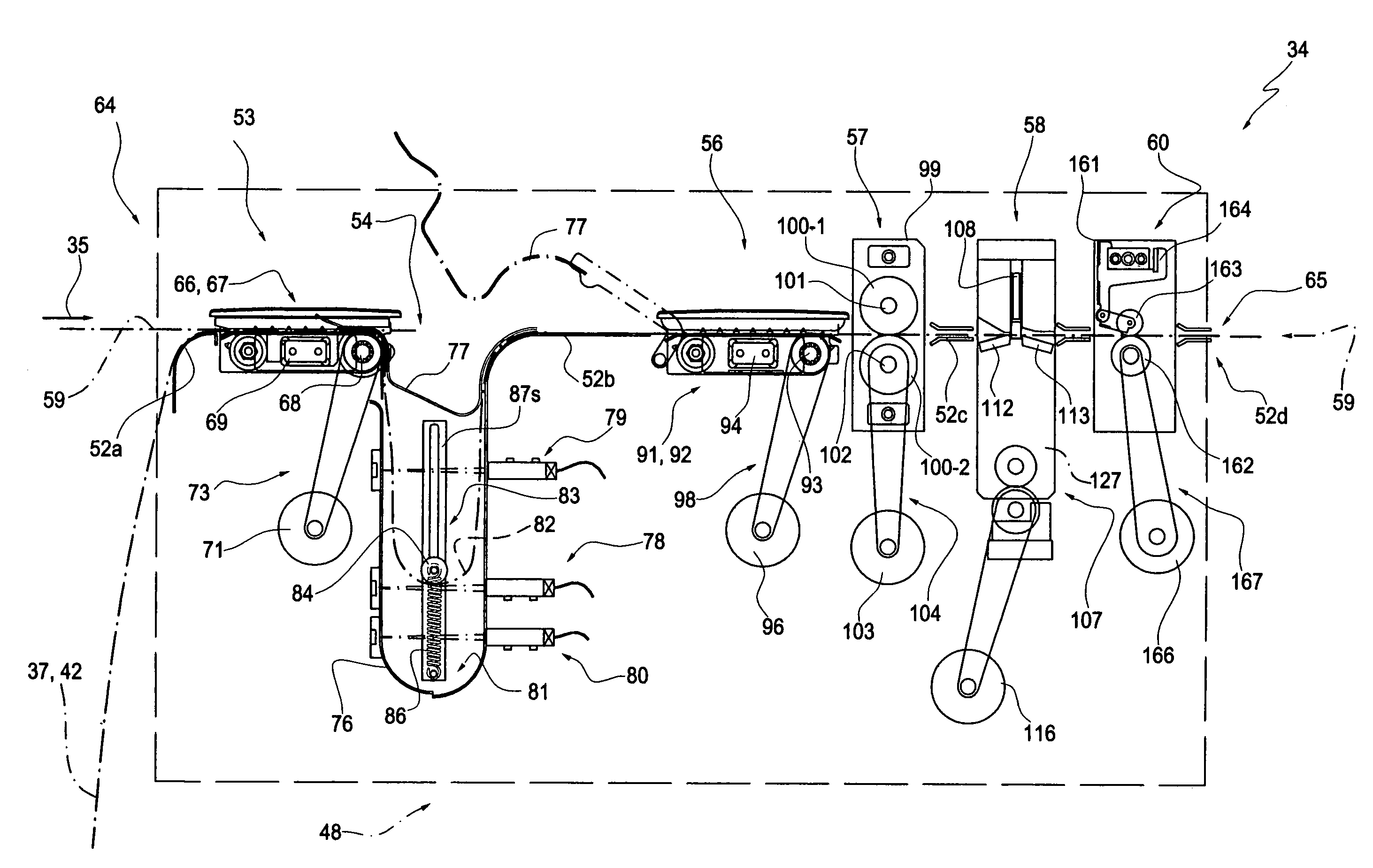
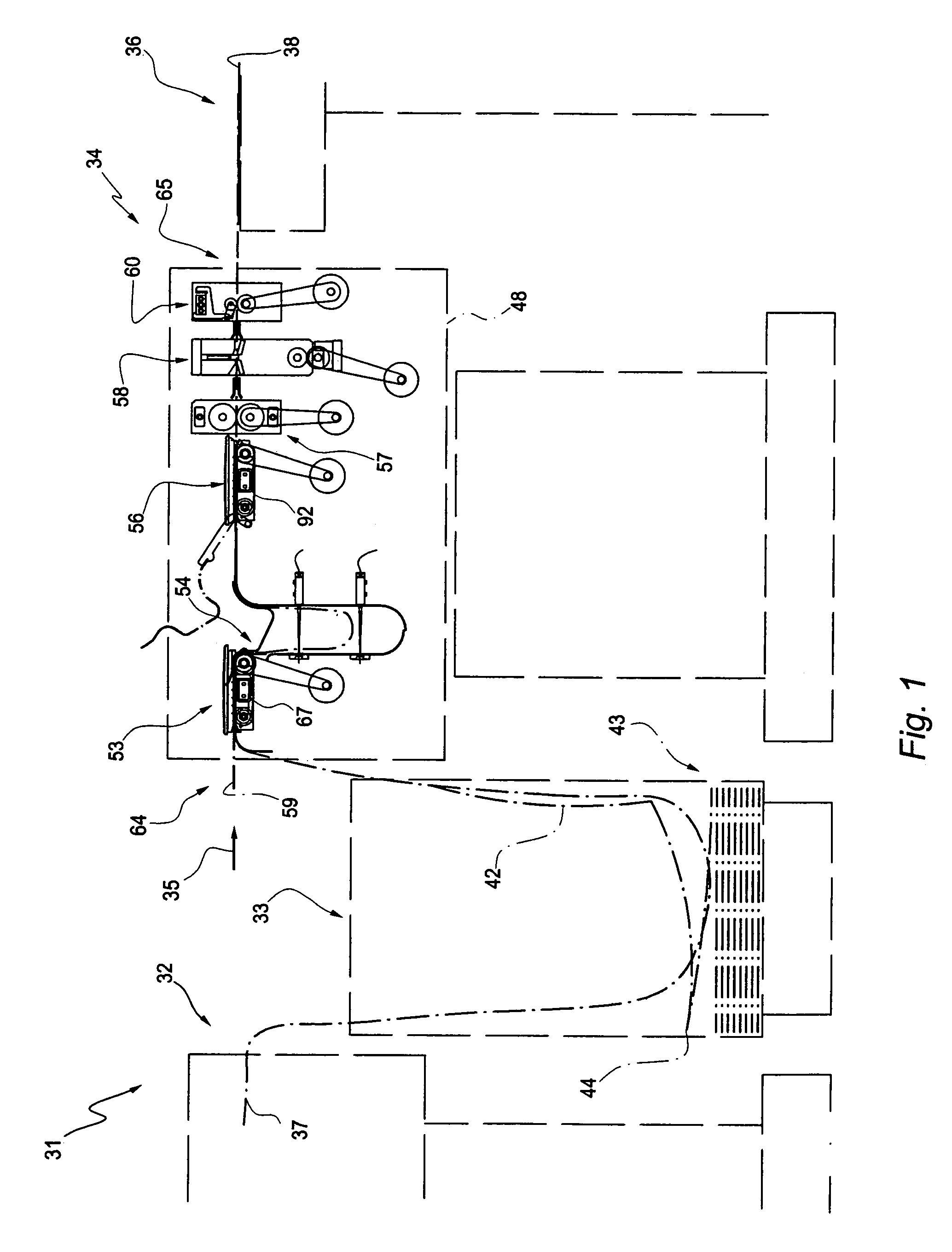
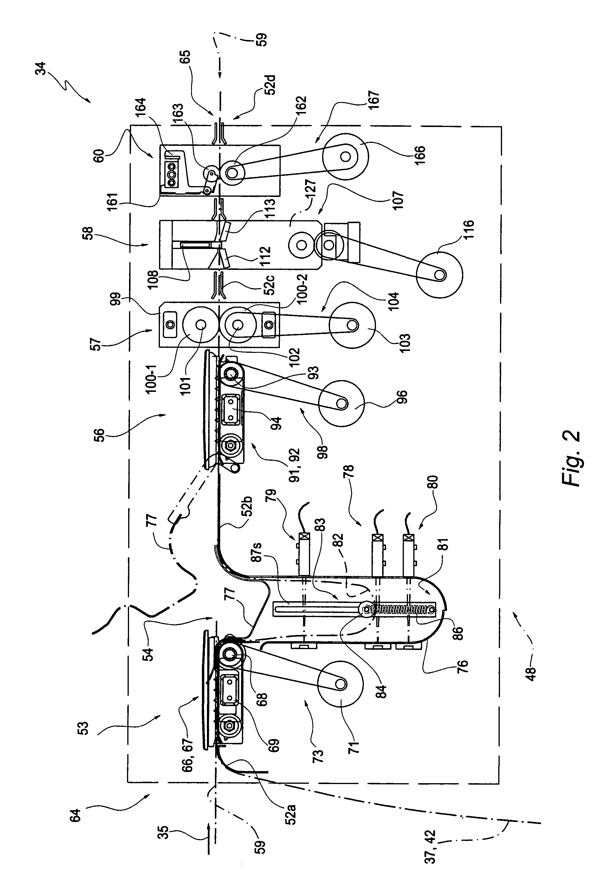
[0044]Represented with 31 in FIG. 1 is a system for the automatic processing of documents comprising a high speed printer 32, a buffer store 33, a cutting equipment 34 and, for instance, a sequencer 36.

[0045]The system 31 uses a continuous form 37 defined in a respective paper web and the cutting equipment 34 is provided to move the web along a direction of movement 35 and separate single sheets 38 from the form 37.

[0046]As far as the present invention it concerns, the continuous form 37 has side sprocket holes 41 (see FIG. 8) and the printer 32 (FIG. 1) is of known type, for instance a laser printer, and provides to print the information regarding the sheets 38 on the form 37. The buffer store 33 can receive long loops of the printed and unprinted form 37 supplied by the equipment 34 and the sequencer 36 is pre-set to arrange, in sequence, the sheets 38.

[0047]The cutting equipment 34 can be used in association with other finishing apparatuses, for instance devices for forming bookl...


PUM

PropertyMeasurementUnit
lengthaaaaaaaaaa
weightaaaaaaaaaa
thicknessaaaaaaaaaa

Abstract

A cutting equipment (34) for continuous forms (37) comprising an input moving device (53) for a continuous form, a loop forming device (54), a cutting feeding device (56) and a transversal cutting mechanism (58) for the form. The form (37) has side sprocket holes (41) and the cutting feeding device (56) includes intermediate pin feed tractors (91, 92) interposed between the loop forming device (54) and the transversal cutting mechanism (58) and provided for cooperating with the sprocket holes of the section of form (37) to be cut. The loop forming device includes a loop sensor (78) and the input moving device (53) causes the form to be entered at a mean velocity depending on the velocity of the intermediate pin feed tractors (91, 92) and on the state of the loop sensor.

Description

FIELD OF THE INVENTION[0001]The present invention relates to a cutting equipment for continuous forms. More specifically, the invention relates to a transversal cutting equipment for continuous forms comprising an input moving device, a loop forming device, a cutting feeding device and a transversal cutting mechanism for the form.BACKGROUND OF THE INVENTION[0002]Cutting equipments of this type are generally used in complex systems for the automatic processing of documents comprising high speed printers and unwinding devices which operate on continuous forms of paper webs. These equipments provide to separate the continuous form into singular or discrete printed documents for the following processing.[0003]For the production of standard documents the times necessary for the cutting of the forms, the separation of the sheets, the finish and the collection of the documents are well longer with respect to the times associated to the print.[0004]In fact, the high speed printers can work ...

Claims


Application Information

Patent Timeline
Patent Type & Authority Patents(United States)
IPC IPC(8): B26D5/20B26D5/28B26D5/40B65H20/22B65H23/188B65H35/06
CPCB65H20/22B65H23/1884B65H35/06Y10T83/2066Y10T83/4594Y10T83/4529Y10T83/0453Y10T83/658
Inventor DE MARCO, GIULIANOAPRATO, ARMANDOTERRUSI, FRANCESCOMASSUCCO, ALBERTO
Owner TECNAU
Why Eureka
Try Eureka