This configuration, however suffers mainly from the
exposure of the active side (side with circuitry and interconnects on it) of the sensor IC die to atmospheric contaminants such as
moisture, dust, and other fluidic and particulate contaminants, many of which are conductive to some extent.
Such conductive
contamination bridging between the electrical interconnects on the surface of the die and the pins and the
package induces stray conduction paths that cause errors in the measurement.
The
silicone gel approach has several disadvantages, for example: 1) It
mass-loads the top of the diaphragm causing increased sensitivity to G forces; 2) the gel is hygroscopic and slowly absorbs water over time thereby negating its potential benefit; 3) the gel deteriorates with time and
environmental exposure, thereby changing its physical characteristics; and 4) the gel adds extreme thermal and pressure
hysteresis to the measurement, thereby limiting its use for precision applications.
Parylene, being a gaseous-deposition ultra-thin
coating performs orders of magnitude better in regard to most of the errors it induces relative to the
silicone gel, however, it still suffers the following drawbacks: 1) It has limited environmental compatibility vs. time, temperature, and compatibility with the pressure media, especially
oxygen and
ozone; and 2) the
parylene film deposited over the sensor diaphragm creates both thermal and pressure
hysteresis due to the mismatch of the
thermal coefficient of expansion between materials.
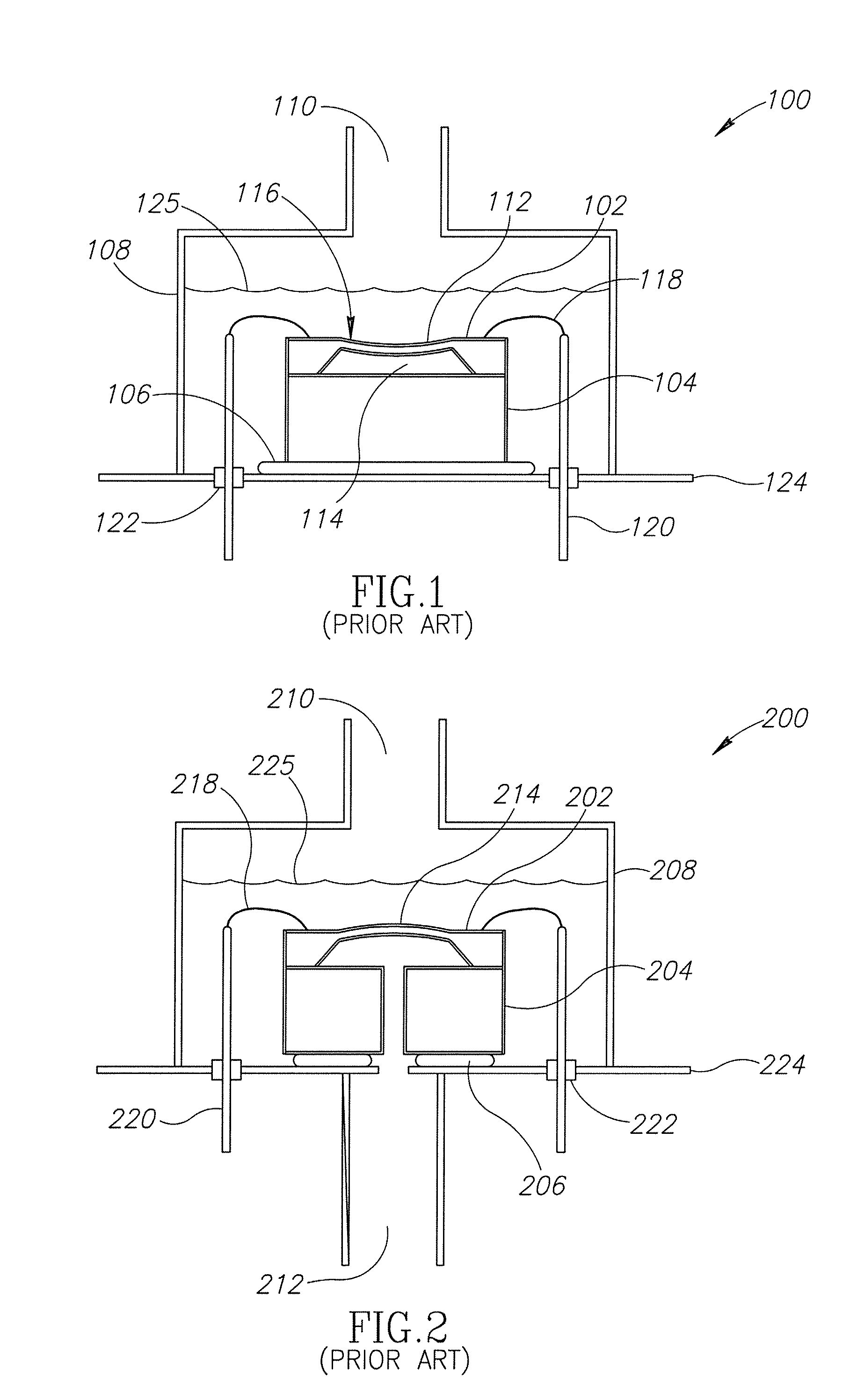
The main drawbacks for the conventional absolute and
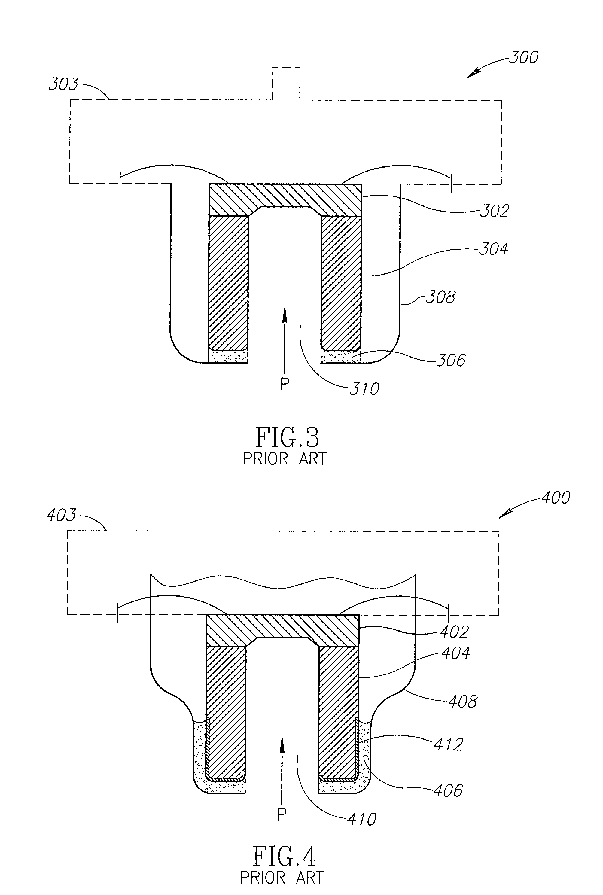
differential pressure sensors described above are the previously discussed performance, reliability and environmental robustness of the sensors due to their packaging approach. FIG. 3 schematically shows a portion of a pressure sensor 300 that alleviates at least some of the previously discussed problems since the
pressure sensing die 302 is not coated with any material that would affect its performance and it also resides within a pristine vacuum environment 303.
An overload of any one of these load conditions may result in a failure of the pressure sensor 300.
Further, repeated loading of the sensor die 302 and
resultant stressing of the solder or
adhesive material may eventually degrade the
structural integrity of the
butt joint 306, causing a non-instantaneous degradation in sensor performance, and in some instances may lead to an instantaneous failure of the pressure sensor 300.
This sensor configuration also has limited life in high vibration environments.
This is due to the limited cross-sectional area of the attachment combined with the cantilevered configuration of the sensor and glass support tube
assembly.
Again and similar to the pressure sensor of FIG. 3, repeated loading of the sensor die 402 and stressing of the
solder material in shear or tension may eventually degrade the
structural integrity of the sleeve-type
hermetic seal 406, causing a non-instantaneous degradation in sensor performance, or, in some instances, may lead to an instantaneous failure of the pressure sensor 400.
However, one drawback of the sleeve joint 406 is that it is still loaded in shear, which limits the amount of pressure up-the-tube to applications of 1000 psi or less.

