Electronic imaging system

a technology of electronic imaging and optical system, applied in the field of electronic imaging system, can solve the problem of the bottleneck in reducing the depth dimension of the camera, and achieve the effects of reducing the preventing the incidence of infrared light on the image pickup plane, and reducing the length and thickness of the optical system

Inactive Publication Date: 2008-10-14
OLYMPUS CORP
View PDF29 Cites 17 Cited by
  • Summary
  • Abstract
  • Description
  • Claims
  • Application Information

AI Technical Summary

Benefits of technology

[0012]To prevent image degradation due to alias while contrast lower than Nyquist frequency is maintained as much as possible, a so-called optical low-pass filter (LPF) is located between a subject and an image pickup device and on the optical path of an optical system, so that a subject image formed by a lens is displaced roughly by a pixel pitch using the double-refraction action of a uniaxial crystal such as rock crystal into a double image, thereby reducing contrast in the vicinity of the Nyquist frequency component.
[0037]Another defect of the CCD or other solid-state image pickup device is that the sensitivity to the wavelength of 550 nm in the near ultraviolet range is considerably higher than that of the human eye. This, too, makes noticeable chromatic blurring at the edges of an image due to chromatic aberrations in the near-ultraviolet range. Such color blurring is fatal to a compact optical system. Accordingly, if an absorber or reflector is inserted onto the optical path, which is designed such that the ratio of the transmittance (τ400) at 400 nm wavelength to that (τ550) at 550 nm wavelength is less than 0.08 and the ratio of the transmittance (τ440) at 440 nm wavelength to that (τ550) at 550 nm wavelength is greater than 0.4, it is then possible to considerably reduce noises such as chromatic blurring while the wavelength range necessary for color reproduction (satisfactory color reproduction) is kept intact.

Problems solved by technology

The gravest bottleneck in diminishing the depth dimension of cameras is the thickness of an optical system, especially a zoom lens system from the surface located nearest to its object side to an image pickup plane.

Method used


Image

  • Electronic imaging system
  • Electronic imaging system
  • Electronic imaging system

Examples


example 1

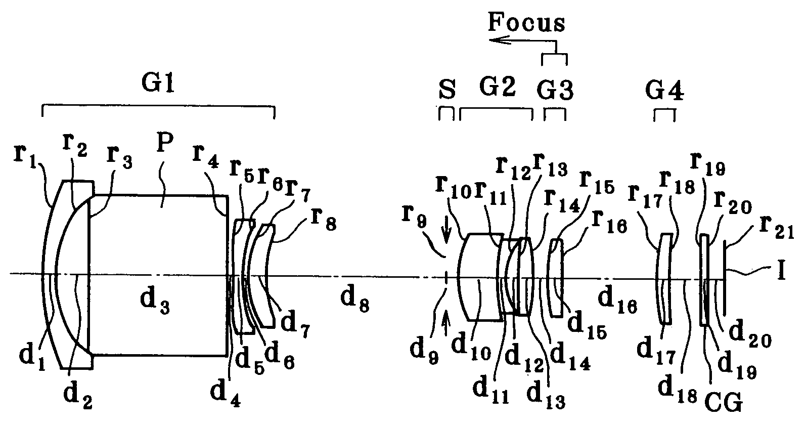
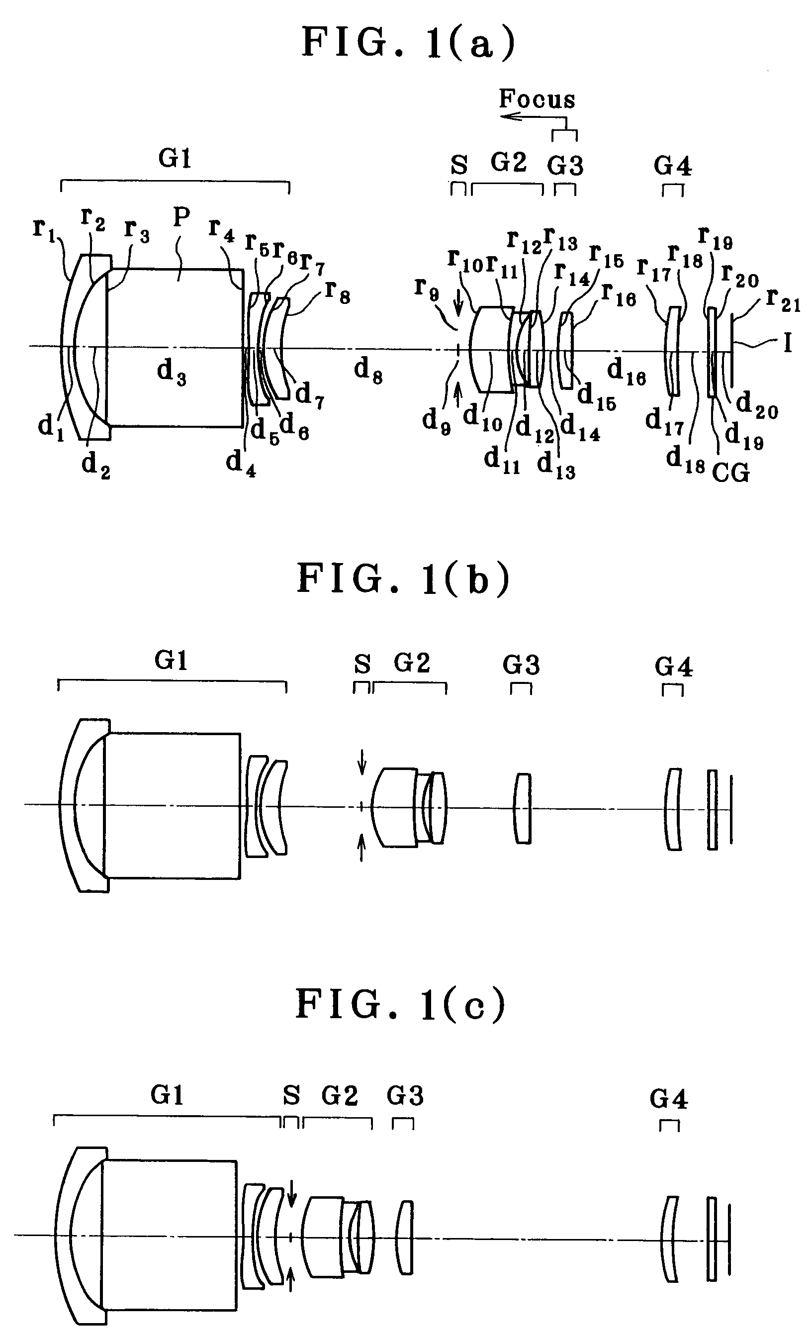
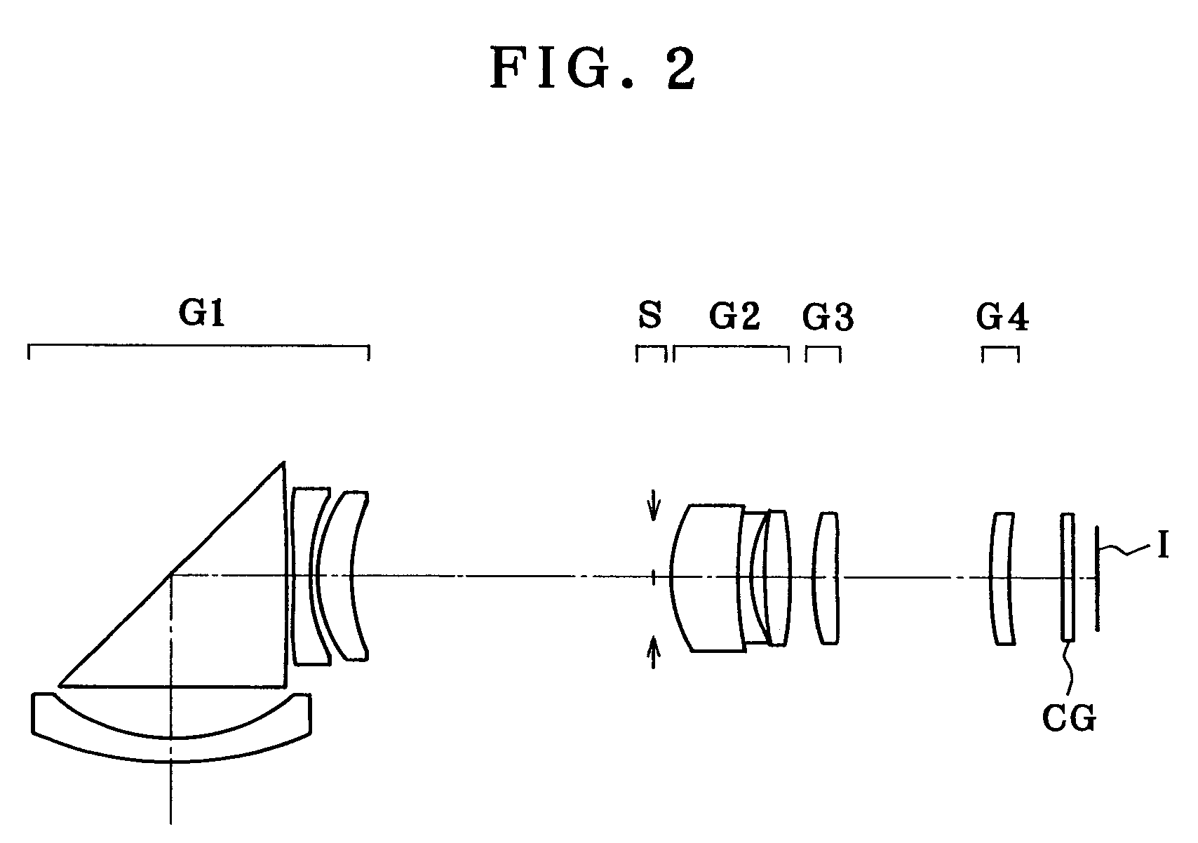
[0077]As shown in FIGS. 1(a), 1(b) and 1(c), Example 1 is directed to a zoom lens made up of a first lens group G1 composed of a negative meniscus lens element convex on its object side, an optical path-bending prism P, a double-concave negative lens and a positive meniscus lens convex on its object side, an aperture stop S, a second lens group G2 composed of a doublet consisting of a positive meniscus lens convex on its object side and a negative meniscus lens convex on its object side and a double-convex positive lens, a third lens group G3 composed of one positive meniscus lens convex on its object side and a fourth lens group G4 composed of one positive meniscus lens convex on its object side. Upon zooming from the wide-angle end to the telephoto end of the zoom lens, the first lens group G1 and the fourth lens group G4 remain fixed, and the aperture stop S, the second lens group G2 and the third lens group G3 move toward the object side. For focusing on a nearby subject, the th...


PUM


Abstract

The invention relates to an electronic imaging system such a video camera or digital camera, whose thickness or size is reduced while performance degradation is reduced as much as possible. The system comprises a zoom lens system comprising a first G1, a second G2, a third G3 and a fourth lens group G4 and an aperture stop S, and an electronic image pickup device located on its image side I and covered with a cover glass CG. The image of a subject is formed on the photoreceptive surface of the electronic image pickup device for conversion into electric signals. The system satisfies the following conditions (1) and (2).a≦4 μm  (1)F>a  (2)Here a is the horizontal pixel pitch in μm of the electronic image pickup device and F is the F-number of the zoom lens system at its wide-angle end.

Description

[0001]This application claims benefits of Japanese Application No. 2002-209560 filed in Japan on Jul. 18, 2002, the contents of which are incorporated herein by this reference.BACKGROUND OF THE INVENTION[0002]In view of the category of the portable low-end type in particular, the primary object of the present invention is to provide the technology for implementing video or digital cameras whose depth dimension is reduced while high image quality is ensured, and which are easy to handle.[0003]The gravest bottleneck in diminishing the depth dimension of cameras is the thickness of an optical system, especially a zoom lens system from the surface located nearest to its object side to an image pickup plane. Recent technologies for slimming down cameras rely primarily on a collapsible lens mount that allows the optical system to be taken out of a camera body for phototaking and received therein for carrying. Typical examples of the zoom lens system so far known to be well fit for electro...

Claims


Application Information

Patent Timeline
Patent Type & Authority Patents(United States)
IPC IPC(8): H04N7/00G02B7/10G02B13/18G02B15/14G02B15/167G03B9/02G03B9/07H04N5/225
CPCG02B15/14G02B15/1445
Inventor MIHARA, SHINICHI
Owner OLYMPUS CORP
Why Eureka
Try Eureka