Airport pavement management system

a technology for managing systems and airports, applied in the direction of vehicles, instruments, etc., can solve the problems of increasing repair costs, generating noise and other complaints, and generating more severe responses, so as to reduce the number of aircraft that overfly, and accelerate the wear and tear

Inactive Publication Date: 2008-10-14
HARRIS CORP
View PDF124 Cites 26 Cited by
  • Summary
  • Abstract
  • Description
  • Claims
  • Application Information

AI Technical Summary

Benefits of technology

[0036]This data can accurately determine how much wear occurs to an airport surface, based upon actual aircraft and other vehicle tracks, as well as ancillary data such as weather and temperature. Calculations are known in the art for determining wear on pavement surfaces based upon actual usage. From such known civil engineering criteria, combined with actual vehicle tracks and vehicle data, the system of the present invention can accurately predict which portions of an airport surface will need resurfacing or repair at what times. Based upon patterns of usage, the system can predict when runways and other paved surfaces will need to be repaired, such that repairs can be bid out, scheduled, and performed before the actual pavement starts to fail, thus minimizing adverse impact on airport operations as well as reducing pavement repair and maintenance costs.

Problems solved by technology

This increase in repair costs varies between two to three times more than it would have cost to repair pavement that was in good condition.
Runway maintenance issues may involve airport staff from accounting, operations, noise and air quality (environmental), air traffic control, and many others.
Aircraft may have to be diverted to non-preferred runways during these maintenance periods and thus causing aircraft to over-fly areas rarely seeing activity during that time period.
These flyovers may generate a number of noise and other complaints and more severe responses if the closures are for longer durations.
The accepted practice for determining the conditions of the pavement at airports is a manually intensive and time-consuming process.
This type of quasi-automation saves some time and labor but still requires physical inspection and closure of the runway, taxiways, or ramp areas.
Acquiring the type of data that these systems need is time consuming, costly, and is labor intensive.
Dismantling the hub-and-spoke routing system may result in the more direct point-to-point flights, which may result in more takeoffs and landings at smaller regional airports, which have less manpower an infrastructure available to monitor pavement conditions on a regular basis.
In addition, the advent of larger airliners such as the Boeing 777 and the Airbus A380 may result in greater wear in runways and taxiways due to the increased weight of these newer aircraft.
Merely counting landings and takeoffs of aircraft may be an insufficient indicia of pavement wear, as these heavier aircraft may cause many times the wear of more traditional, smaller aircraft.
Thus, for example, if prevailing winds at an airport are consistently from one direction, one runway (or set of runways) may experience substantially more wear than other, lesser-used runways.
Repaving all runways and taxiways after a predetermined amount of time or after a predetermined number of takeoff / landing cycles may represent an inefficient use of airport maintenance resources, as some runways and taxiways may experience considerable wear, while others are still in usable condition.
Moreover, using such arbitrary criteria to determine pavement condition may fail to detect pavement degradation in some frequently used taxiways and runways.

Method used


Image

  • Airport pavement management system
  • Airport pavement management system
  • Airport pavement management system

Examples


Embodiment Construction

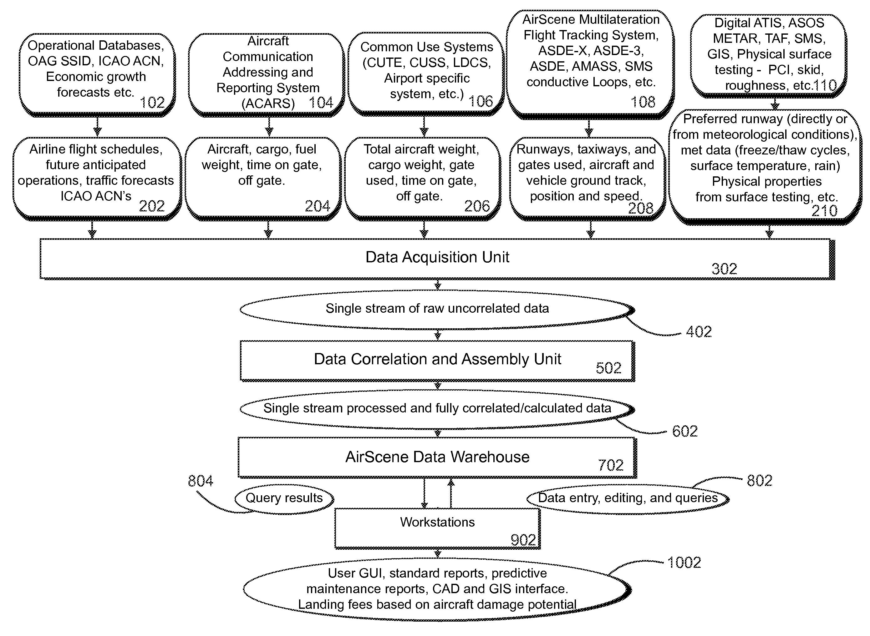
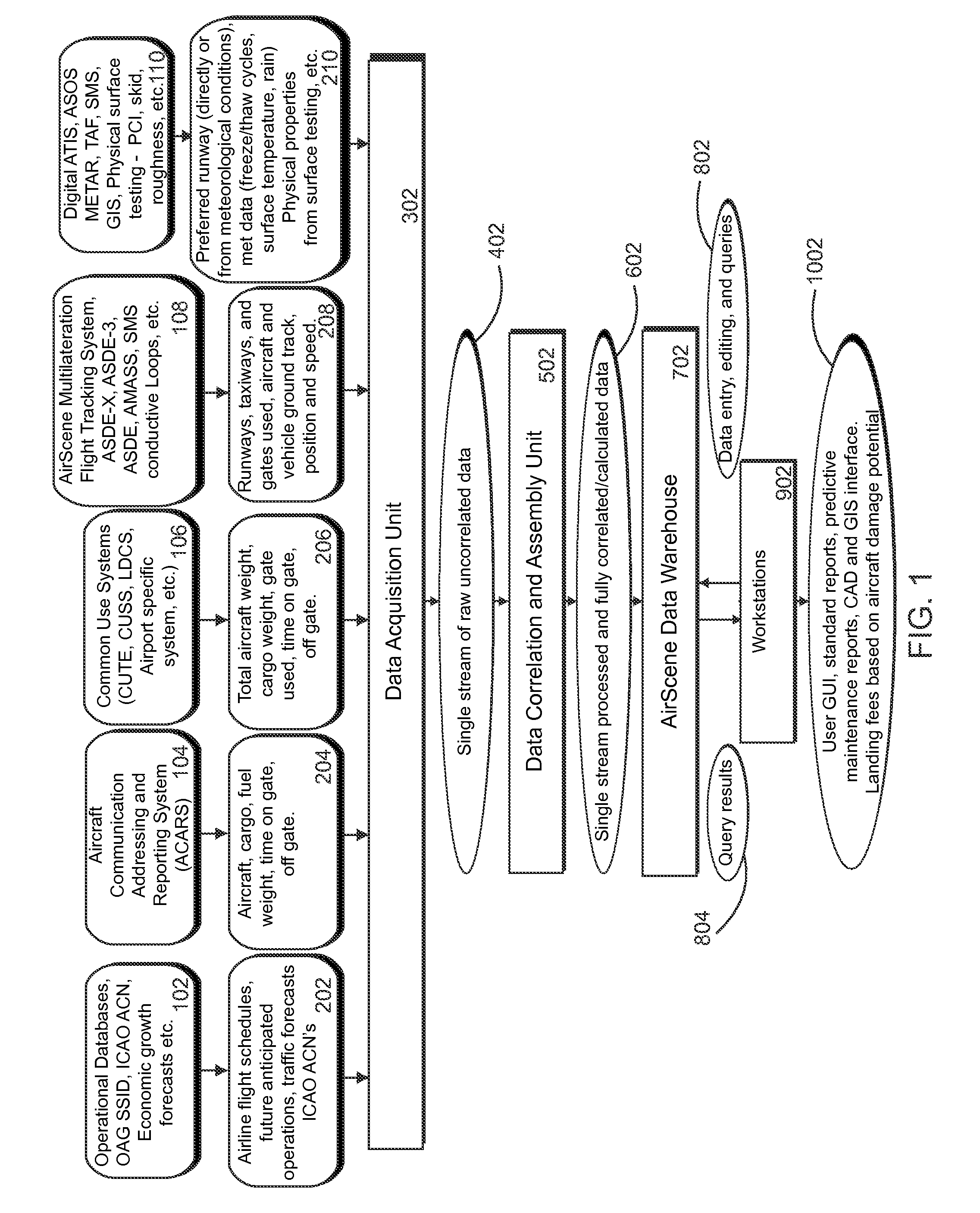
[0045]FIG. 1 is a block diagram illustrating the major components of the AirScene™ Pavement Management System and the types of data that are utilized. The AirScene™ Pavement Management System utilizes this data to quantify the pavement damage caused each individual aircraft movement. This cumulative data allows AirScene™ to compute pavement condition based on an initial survey and the calculations of accrued damage. This information can be displayed through AirScene™ in the form of tables, graphs, or graphically represented on an airport diagram. The display can show current conditions, rates of accruing damage, and future wear rates and areas.

[0046]Referring to FIG. 1, the system draws on data from the AirScene™ Data Warehouse (ADW). The ADW represents a single repository for all the information acquired from a number of different data sources. These data sources may include operational databases 102, from data 202 may include airline flight schedules, future anticipated operations...


PUM


Abstract

The AirScene™ Pavement Management System of the present invention automatically tracks data required to determine various factors in an assessment of current and future pavement maintenance needs and utilizes this data to quantify the pavement damage caused by each individual aircraft movement and thus compute pavement condition based on an initial survey and the calculations of accrued damage over time. This information can be displayed through AirScene™ in the form of tables, graphs, or graphically represented on an airport diagram showing present conditions, rates of accruing damage, and future wear rates and areas. The system draws on the data from the AirScene™ Data Warehouse (ADW), a single repository for all the information acquired from a number of different sources. These data include: Aircraft or vehicle type (wheel layout, weight, vehicle specific parameters, and the like), Aircraft or vehicle location (ground track, position, gate used, and the like), Aircraft or vehicle dynamics (velocity, acceleration, take off, touchdown, and the like), Aircraft or vehicle actual weight (cargo load, fuel load, and the like), as well as Future operational data (flight schedules, increasing flight loads and demand, and the like).

Description

CROSS-REFERENCE TO RELATED APPLICATIONS[0001]The present application is a Continuation-In-Part application of U.S. patent application Ser. No. 10 / 743,042, filed on Dec. 23, 2003, now U.S. Pat. No. 7,132,982 and incorporated herein by reference; U.S. patent application Ser. No. 10 / 743,042 in turn is a Continuation-In-Part Application of U.S. patent application Ser. No. 10 / 638,524, filed on Aug. 12, 2003, entitled “METHOD AND APPARATUS FOR IMPROVING THE UTILITY OF AUTOMATIC DEPENDENT SURVEILLANCE”, now U.S. Pat. No. 6,806,829, which is incorporated herein by reference in its entirety, which in turn is a Continuation of U.S. patent application Ser. No. 09 / 516,215, filed on Feb. 29, 2000, now U.S. Pat. No. 6,633,259, which in turn claims priority from Provisional Application Ser. No. 60 / 123,170, filed on Mar. 5, 1999, both of which are incorporated herein by reference in its entirety; U.S. patent application Ser. No. 10 / 743,042 is also a Continuation-In-Part of U.S. patent application S...

Claims


Application Information

Patent Timeline
Patent Type & Authority Patents(United States)
IPC IPC(8): G01B3/44E01C7/00
CPCE01C23/00
Inventor BREEN, THOMAS J.SMITH, ALEXANDER E.
Owner HARRIS CORP
Why Eureka
Try Eureka