
Localization mechanism for an MRI compatible biopsy device

a biopsy probe and localization mechanism technology, applied in medical science, surgery, vaccination/ovulation diagnostics, etc., can solve the problems of affecting the use of mri guidance, creating field distortion, and no single procedure is ideal for all cases

Inactive Publication Date: 2008-10-21
DEVICOR MEDICAL PROD
View PDF40 Cites 63 Cited by
  • Summary
  • Abstract
  • Description
  • Claims
  • Application Information

AI Technical Summary

Benefits of technology

[0019]The invention provides an apparatu

Problems solved by technology

The type of biopsy used depends mainly on various factors present in the patient, and no single procedure is ideal for all cases.
However, existing medical biopsy sampling devices use small, multi-lumen probes extensively fabricated mostly if not entirely from metal.
Typically these metal probes are electrically conductive and often magnetically weak, which interferes with their use under MRI guidance.
The electrically conductive and magnetically weak nature of metal probes often work to create field distortions, called artifacts, on the image.
The image of the lesion will show the metal probe, and this is problematic because the image of the probe can obscure the image of the lesion.
The small sample size of conventional biopsy needles also presents a significant limitation due to the increase in the duration of the procedure.
This limits the number of samples that can be retrieved using conventional spring-loaded core biopsy needles under direct imaging guidance.
A further problem not infrequently encountered during core needle biopsy is the development of a hematoma at the biopsy site during the procedure.
An accumulating hematoma can be problematic during MRI-guided biopsy because residual contrast agent circulating in the hematoma can mimic enhancement in a suspicious lesion.
In addition, the accumulation of air at the biopsy site can cause susceptibility artifacts that can potentially interfere with the fat-suppression MRI techniques at the biopsy site cavity.
These limitations of conventional biopsy needles have led several authors to conclude that lesions should be at least 1 cm in diameter before imaging could confirm that the MRI-guided biopsy device was definitely within (as opposed to adjacent to) the suspicious target.
However, the demand for minimally invasive MRI-guided core biopsy is greatest for small lesions because they are more common, more difficult to characterize on MRI grounds alone, and have the best prognosis if they are found to be malignant.
However, elimination of the artifact created by the metal probe entirely is also problematic because physicians rely extensively on some type of artifact to notify them as to where the tip of the probe is relative to the lesion.
For instance, the hand-held biopsy device presents a long, external handle that is inappropriate for closed magnet MRI machines.
However, the angle and depth of insertion the probe tends to vary, especially without continual reimaging of the probe during insertion, which is particularly inappropriate for closed MRI magnets.

Method used


Image

  • Localization mechanism for an MRI compatible biopsy device
  • Localization mechanism for an MRI compatible biopsy device
  • Localization mechanism for an MRI compatible biopsy device

Examples


Embodiment Construction

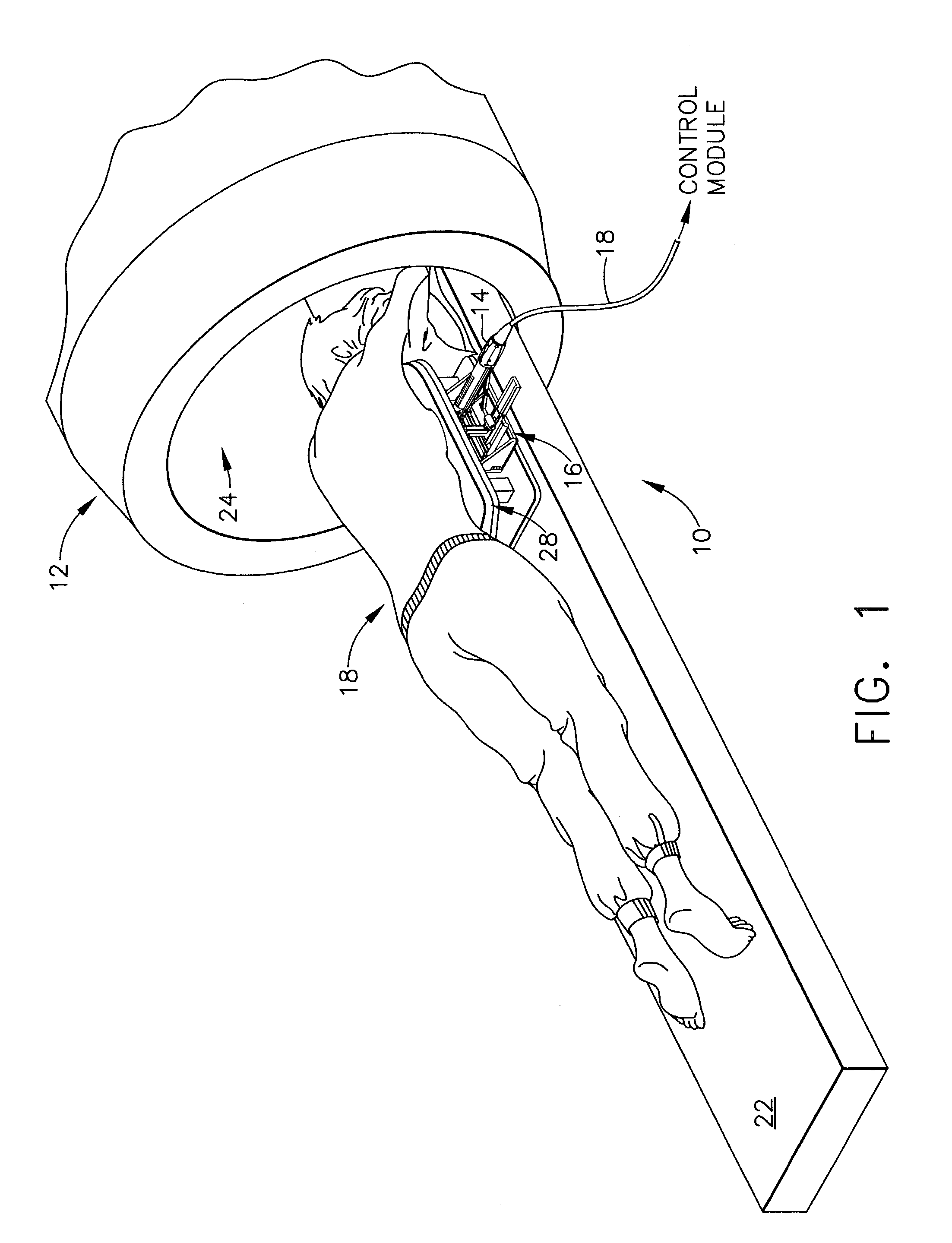
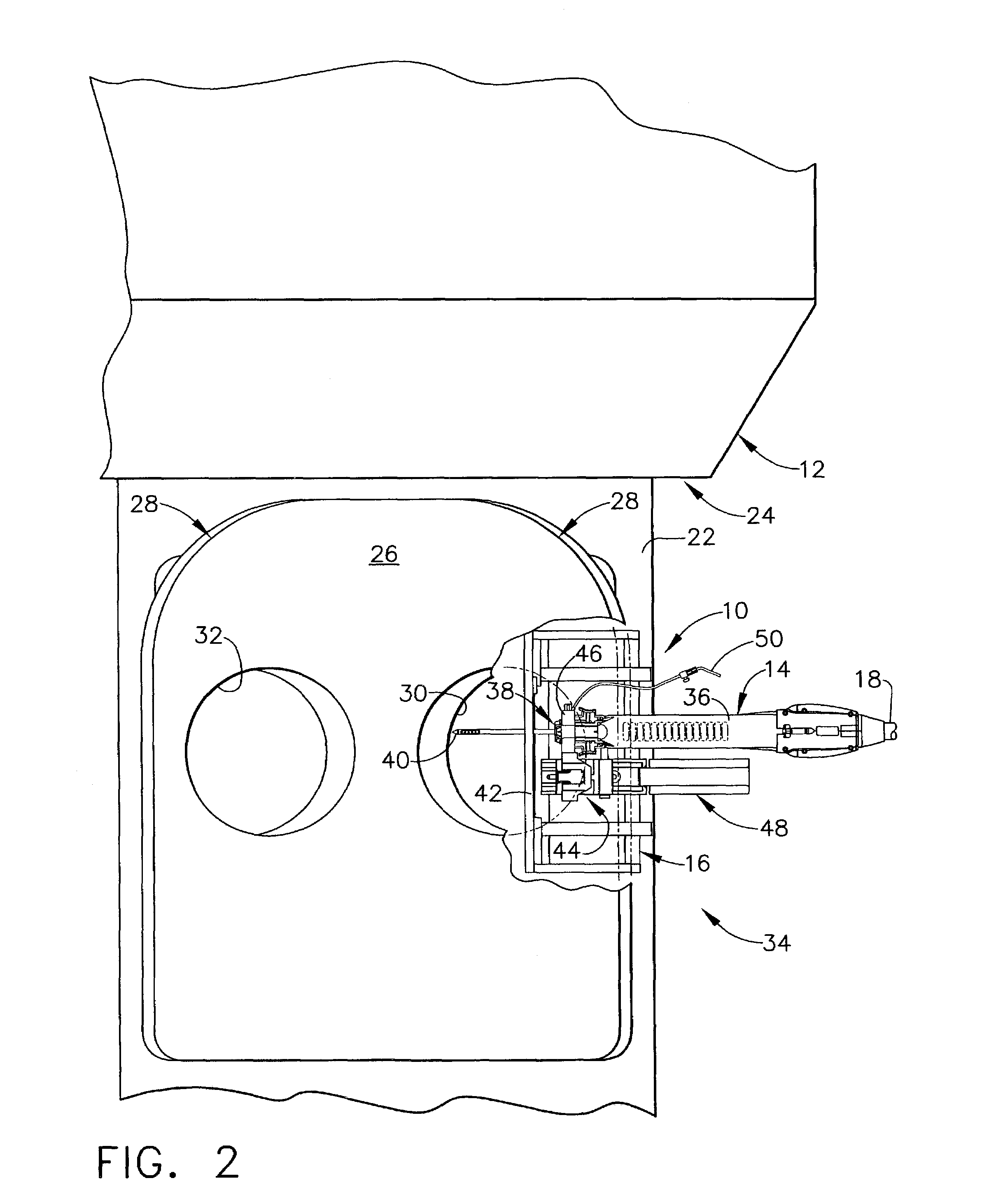
[0051]FIGS. 1 through 21 and the accompanying description are taken from the above referenced US Patent Application “Localization Mechanism for an MRI Compatible Biopsy Probe Device” Ser. No. 10 / 171,330 filed Jun. 12, 2002.

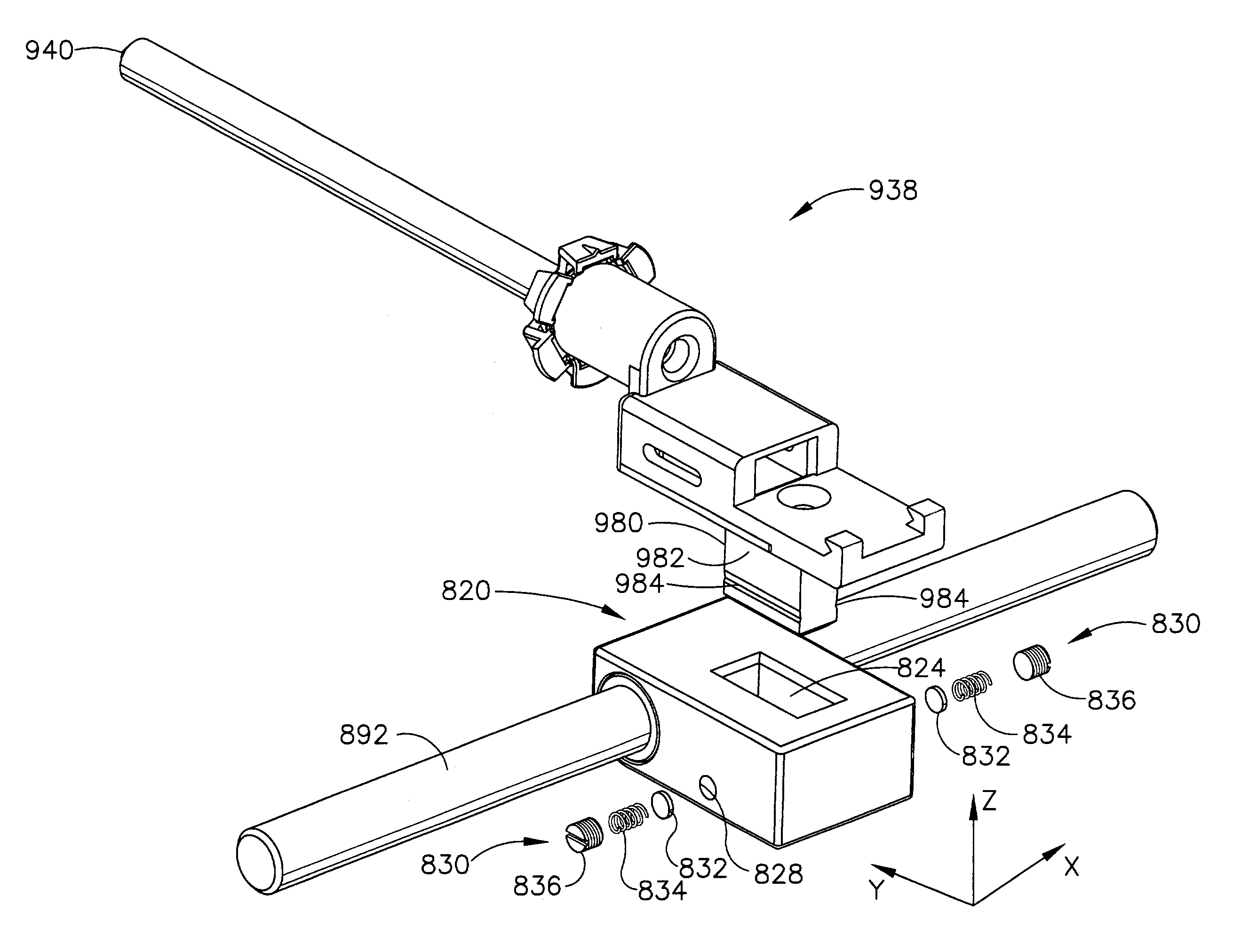
[0052]FIG. 1 depicts a core biopsy instrument system 10 that is vacuum assisted, detachable, and compatible with use in a Magnetic Resonance Imaging (MRI) machine, such as the depicted closed MRI machine 12. In the illustrative embodiment, the core biopsy instrument system 10 includes an MRI-compatible biopsy tool 14 that is selectably attached to a localization mechanism or fixture 16 to accurately and rapidly perform core biopsies of breast tissue with a minimum of insertions of a biopsy probe. A control module (not shown) senses encoder position signal and switch signals from the biopsy tool 14 and provides mechanical and vacuum power to the biopsy tool 14 via power cord 18.

[0053]With reference to FIGS. 1-2, a patient 20 is lying prone upon a patient support ta...


PUM


Abstract

A localization mechanism, or fixture, is used in conjunction with a breast coil for breast compression and for guiding a core biopsy instrument during prone stereotactic biopsy procedures in both open and closed Magnetic Resonance Imaging (MRI) machines. The localization fixture can include a breast compression plate and a biopsy probe support plate for supporting a biopsy probe for movement along multiple perpendicular axes. The position of both the breast compression plate and the biopsy probe support plate can be adjustable along an axis which is generally parallel to a probe needle.

Description

CROSS REFERENCE TO RELATED APPLICATIONS[0001]The present application cross references and incorporates by reference copending U.S. Ser. No. 10 / 171,330, “LOCALIZATION MECHANISM FOR AN MRI COMPATIBLE BIOPSY DEVICE” filed on Jun. 12, 2002, the disclosure of which is hereby incorporated by reference in their entirety.FIELD OF THE INVENTION[0002]The present invention relates, in general to devices for tissue sampling and, more particularly, to a device for positioning a biopsy probe with respect to a magnetic resonance imaging (MRI) device.BACKGROUND OF THE INVENTION[0003]The diagnosis and treatment of patients with cancerous tumors, pre-malignant conditions, and other disorders has long been an area of intense investigation. Non-invasive methods for examining tissue are palpation, Thermography, PET, SPECT, Nuclear imaging, X-ray, MRI, CT. and ultrasound imaging. When the physician suspects that tissue may contain cancerous cells, a biopsy may be done either in an open procedure or in a ...

Claims


Application Information

Patent Timeline
IPC IPC(8): A61B10/00A61B10/02A61B17/00A61B17/34A61B19/00
CPCA61B10/0275A61B17/3403A61B19/201A61B2017/00398A61B2017/00477A61B2017/008A61B2017/3411A61B2017/347A61B2019/205A61B2019/5433A61B2019/5454A61B90/17A61B90/11A61B2090/3933A61B2090/3954
Inventor TSONTON, MARKTINSLEY, III, JOHN C.THOMPSON, ERIC W.
Owner DEVICOR MEDICAL PROD
Learn More