Screening optical transceiver modules for electrostatic discharge damage

a technology of optical transceiver and electrostatic discharge, which is applied in the direction of individual semiconductor device testing, testing circuits, instruments, etc., can solve the problems of being very susceptible to electrostatic discharge damage, general much more difficult than electrical communication, and affecting the performance of optical transceiver modules

Active Publication Date: 2008-10-21
II VI DELAWARE INC
View PDF31 Cites 16 Cited by
  • Summary
  • Abstract
  • Description
  • Claims
  • Application Information

AI Technical Summary

Benefits of technology

[0018]FIG. 3 illustrates a transceiver module wherein the control circuitry within the t

Problems solved by technology

Light signals are more secure because they do not allow portions of the signal to escape from the fiber optic cable as can occur with electrical signals in wire-based systems.
While there may be an evanescent field that enables one to siphon some portion of the light off the fiber by bending the fiber such that it is possible to tap fiber communications without breaking the fiber, it is in general much more difficult than for electrical communications.
While the oxide lasers diodes exhibit some desirable characteristics, they also have the unfortunate drawback of being very susceptible to electrostatic discharge (ESD) damage.
This is easy to predict since the lattice disruption confinement technique disrupts the layers all the way through the VCSEL structure, while the oxide confinement technique only creates a very thin dielectric layer.
Whereas most typical electronics have an ESD resistance of least 500 V and often much higher, the oxide VCSEL is susceptible to ESD damage at voltages as low as 200 V or less.
Another difficulty with ESD damage to oxide VCSELs is that such damage is often latent, meaning that it is not immediately detectable sim

Method used


Image

  • Screening optical transceiver modules for electrostatic discharge damage
  • Screening optical transceiver modules for electrostatic discharge damage
  • Screening optical transceiver modules for electrostatic discharge damage

Examples


Embodiment Construction

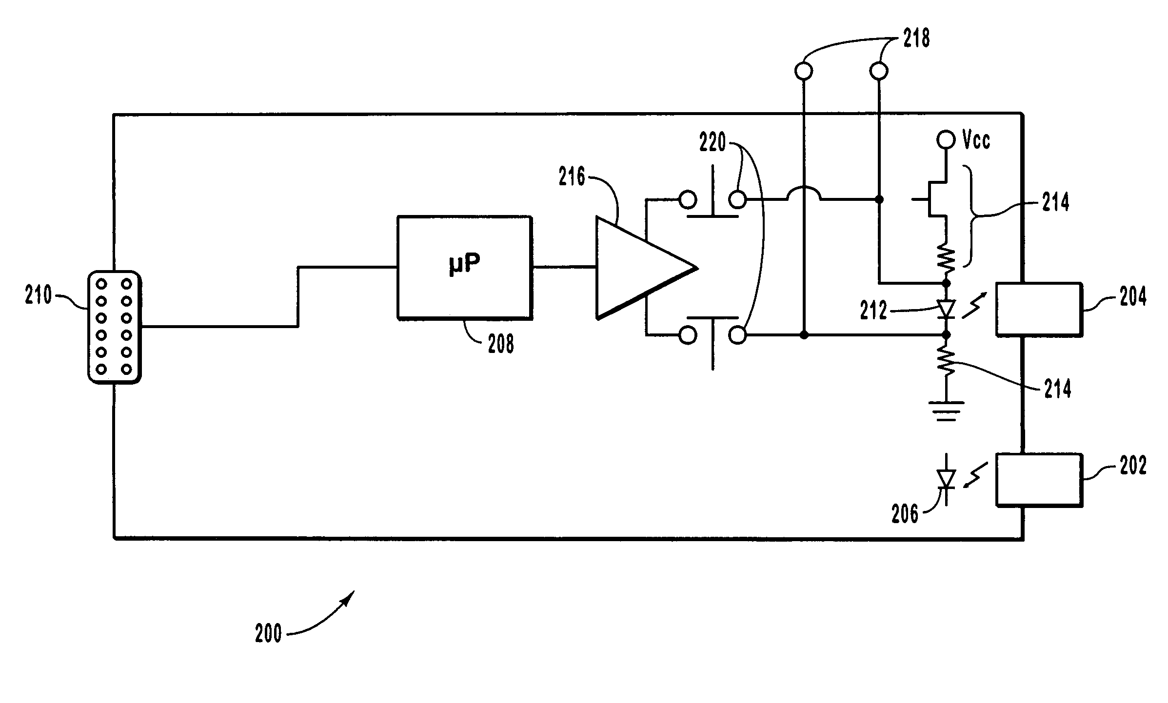
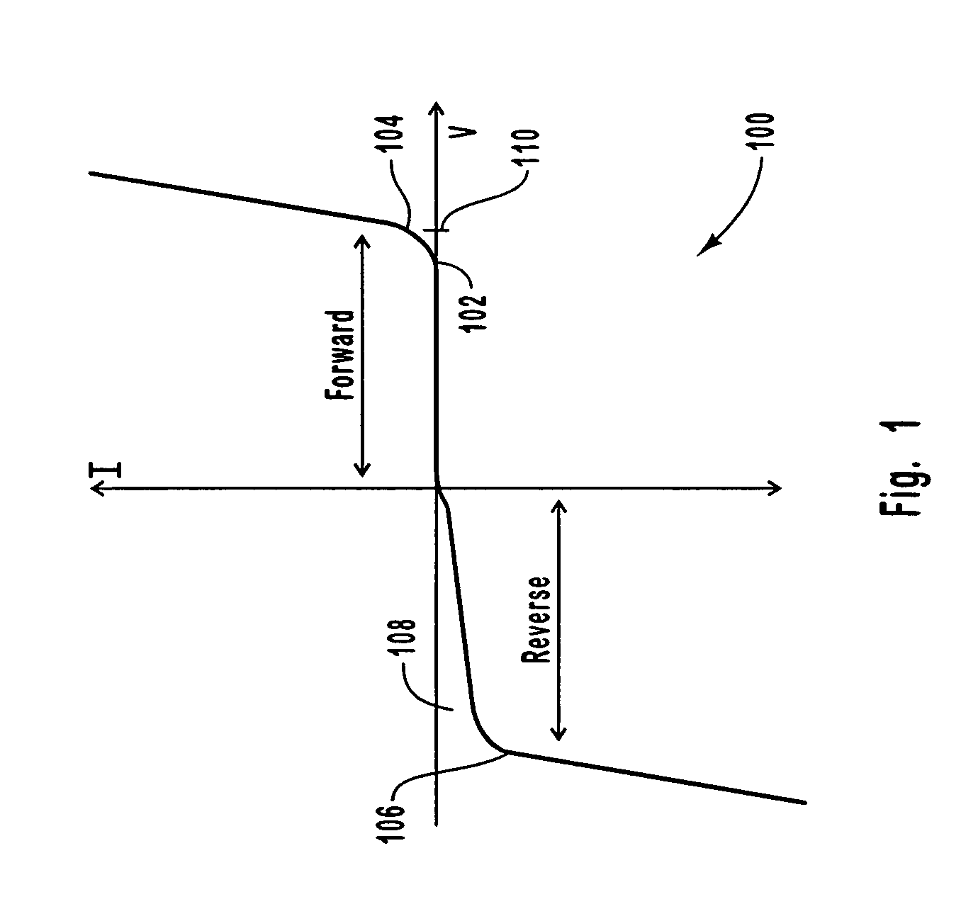
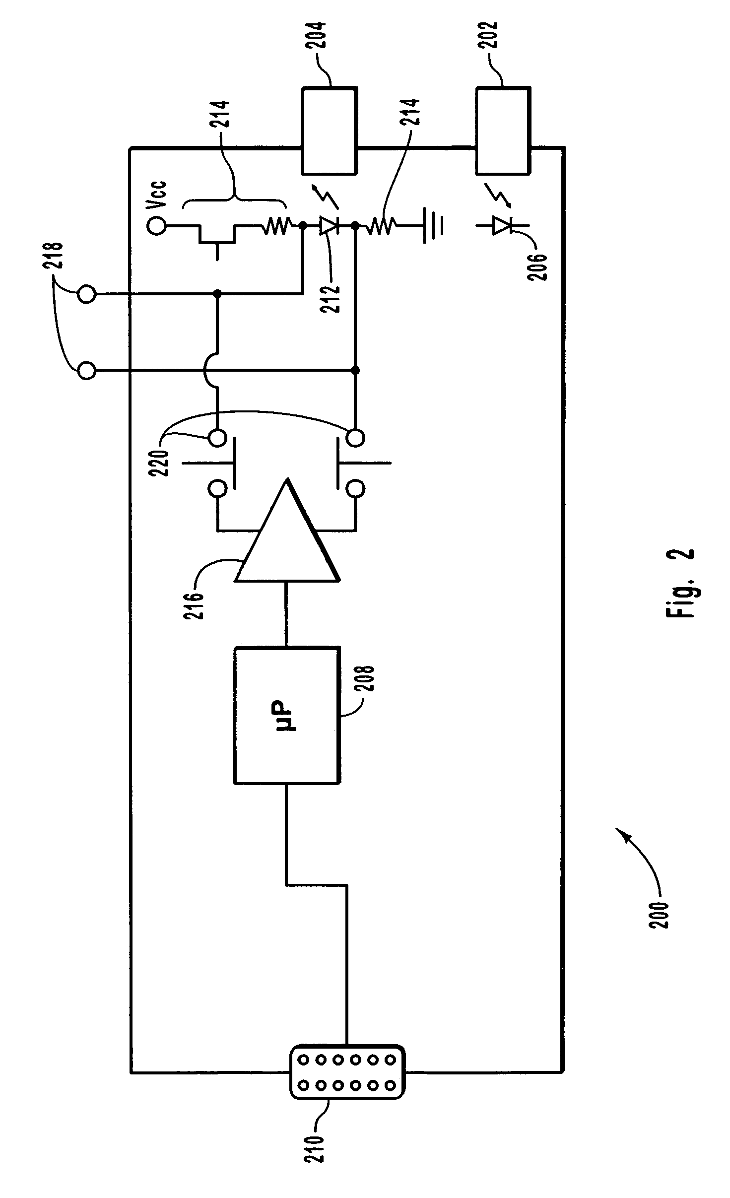
[0019]Embodiments of the present invention provide apparatus for testing a laser diode including oxide VCSELs, which have been installed in transceivers, over time to determine if damage has occurred to the laser diode. One embodiment of the invention allows for the laser diode to be separated from other circuitry such that test equipment can be attached to the laser diode. An operating characteristic such as current / voltage characteristics or current versus optical power characteristics of the laser diode can be measured and recorded for comparison with subsequent measurements or a reference measurement. In another embodiment of the invention, a laser driver in the transceiver includes circuitry for measuring current / voltage, current versus power and / or other characteristics of the laser diode. The measured characteristics may be stored in memory on the transceiver for comparison, with subsequent measurements or a reference measurement. The comparison may be accomplished by using a...


PUM


Abstract

A general method is given for screening laser diodes for electrostatic discharge, (ESD), damage. The laser diode may be selectively isolated from the laser driver so that a current-voltage (I-V), curve can be taken and then compared to curves taken previously on the same laser diode to ascertain the possibility of ESD damage. Presumably the initial I-V curve will be representative of the characteristics of that particular laser in the undamaged state. Such an initial curve may be supplied by the manufacturer and may be a curve specific to a particular laser diode. Comparison with a standard curve is not sufficient to determine ESD damage in the early stages of failure. Some embodiments focus on isolating the laser diode from the laser driver, storing the information locally in the transceiver, and providing some analysis resulting in flagging laser diodes showing changes that are indicative of ESD damage.

Description

CROSS REFERENCE TO RELATED APPLICATION[0001]This application claims the benefit of U.S. Provisional Application No. 60 / 444,486 filed Feb. 3, 2003 which is incorporated herein by reference.BACKGROUND OF THE INVENTION[0002]1. The Field of the Invention[0003]The present invention relates to screening vertical cavity surface emitting lasers (VCSELs) for quality control purposes. More specifically, the invention relates to methods and apparatus for testing VCSELs that have been installed in transceiver modules in which damage to the laser may have taken place either during the installation into the transceiver module or some time after installation into the transceiver module.[0004]2. Description of the Related Art[0005]In the field of data transmission, one method of efficiently transporting data is through the use of optical fibers. Digital data is propagated through a fiber optic cable using light emitting diodes or lasers. Light signals allow for extremely high transmission rates and...

Claims


Application Information

Patent Timeline
IPC IPC(8): G01R27/28H04B10/00
CPCG01R31/002G01R31/2635
Inventor HOFMEISTER, RUDOLF J.MIAO, SONGWEBER, ANDREASFREEMAN, WILLIAM
Owner II VI DELAWARE INC
Why Eureka
Try Eureka