
Apparatus and method for the reduction of bone fractures

a bone fracture and apparatus technology, applied in the field of bone fracture reduction, can solve the problems of reducing open fractures with substantial risks to patients, joint stiffness, and potentially serious functional restrictions affecting daily living, so as to reduce bone fractures, avoid drawbacks, and reduce the effect of fractures

Active Publication Date: 2008-10-28
BEHRENS ALFRED F
View PDF12 Cites 44 Cited by
  • Summary
  • Abstract
  • Description
  • Claims
  • Application Information

AI Technical Summary

Benefits of technology

[0007]The present invention provides instruments and method for enabling effective reduction of bone fractures utilizing minimally invasive techniques, thereby avoiding drawbacks of open reduction and current percutaneous procedures. As such, the present invention attains several objects and advantages, some of which are summarized as follows: Enables minimally invasive procedures for the reduction of bone fractures by virtue of requiring only small openings in soft tissue and bone for the introduction, manipulation and removal of instruments constructed for carrying out percutaneous techniques for bone fracture reduction; provides instruments having broad working configurations relative to narrow insertion configurations to accomplish effective support and movement of bone fracture fragments into reduced positions at a bone fracture site accessed through a minimally invasive access passage; allows for simplified manipulation of a working head from a remote location to rotate and translate bone fracture fragments in multiple directions for minimally invasive bone fracture reduction, and especially in the management of bone fractures and bone conditions located near joints of the body (peri-articular fractures) and fractures that involve joint surfaces (intra-articular fractures); allows the reduction of relatively large fractured joint surfaces, percutaneously, using only arthroscopic or radiographic visualization methods in minimally invasive procedures; avoids risks and complications which otherwise could arise out of open reduction procedures, such as soft tissue necrosis and bone infections; reduces operating times and blood loss; enables a reduction in the length of a hospital stay and, in some instances, avoids hospitalization entirely; reduces recovery time and patient discomfort; avoids excessive joint stiffness and potentially serious functional restrictions affecting daily living, as well as work and recreational pursuits.

Problems solved by technology

Despite careful operative procedures, such open reduction carries substantial risks to the patient, ranging from soft tissue necrosis to deep wound and joint infections.
Even where incisions heal well, scarring of the transected tissues is inevitable and can result in joint stiffness and potentially serious functional restrictions affecting daily living, as well as work and recreational pursuits.
Although these techniques can avoid some of the complications afflicting open reduction, to date such techniques have been successful only in the reduction of simple fractures, such as splits and some depressions.
Thus, bone punches permit only unidirectional motion and concomitant unidirectional movement of bone fracture fragments.
As a result, when attempting to reduce bone fracture fragments, and especially comminuted bone fracture fragments, rather than pushing the bone fracture fragments into a desired position, bone punches tend to slide through gaps between the bone fracture fragments and penetrate into the joint itself, rendering the punches ineffectual and even potentially harmful to the joint.
Larger diameter punches would require corresponding larger diameter bone openings for enabling introduction of the punches, presenting a danger of developing stress fractures at the level of the entry holes, such stress fractures being an unacceptable condition.

Method used


Image

  • Apparatus and method for the reduction of bone fractures
  • Apparatus and method for the reduction of bone fractures
  • Apparatus and method for the reduction of bone fractures

Examples


Embodiment Construction

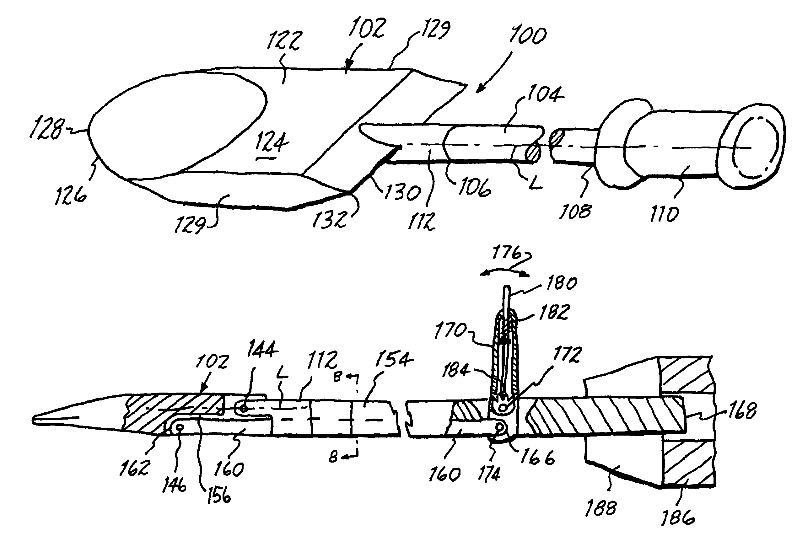
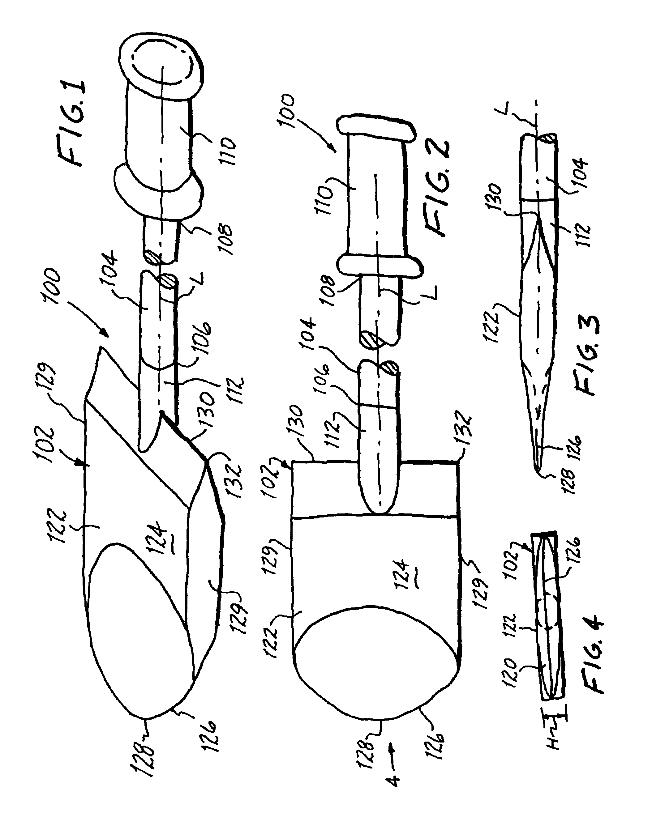
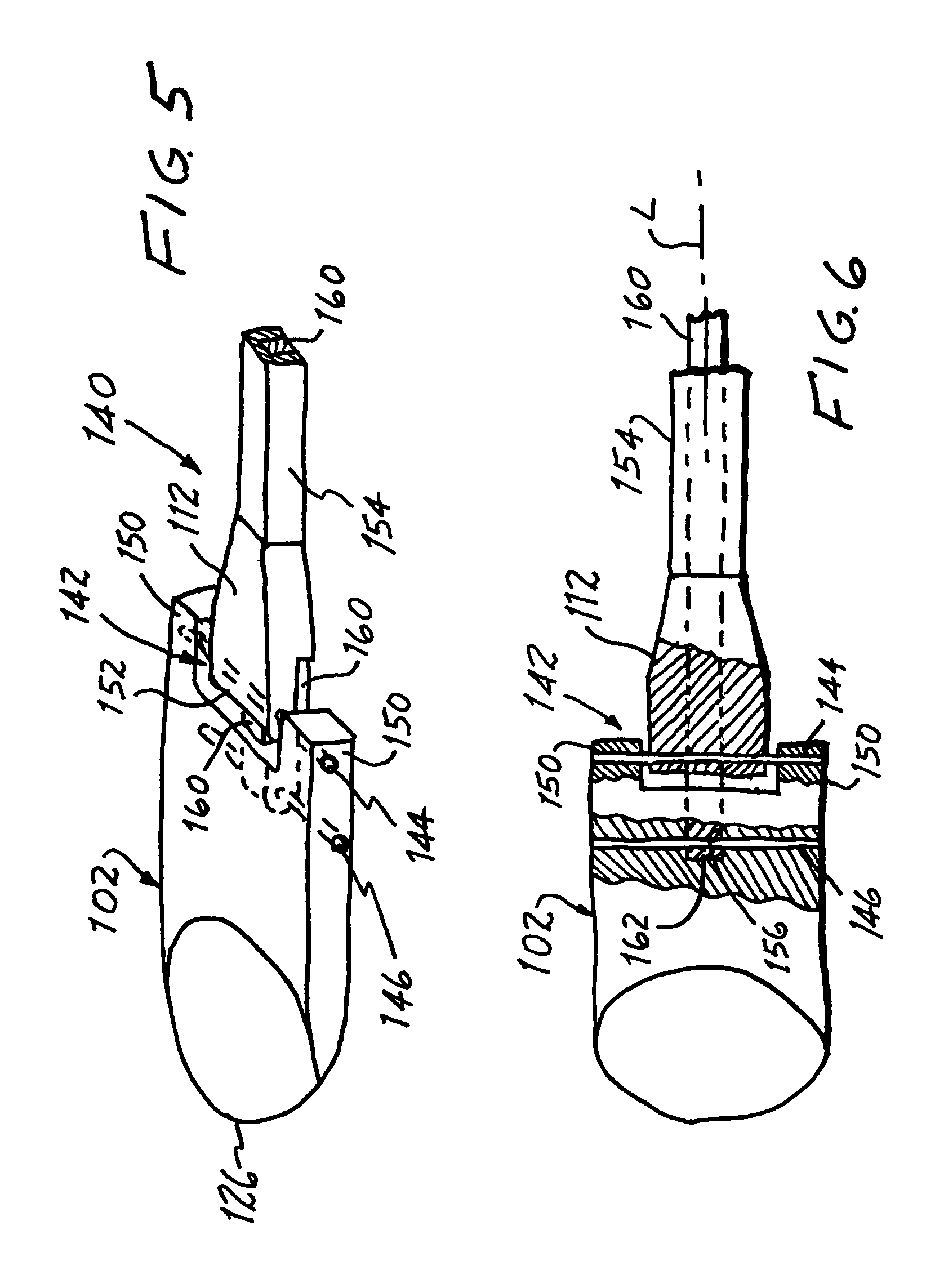
[0050]Referring now to the drawing, and especially to FIGS. 1 through 4, an instrument constructed in accordance with the present invention is illustrated at 100 and is seen to have a working head 102 and a stem 104, the stem 104 extending along a longitudinal axis L between a first end 106 connected to the working head 102 and a second end 108 remote from the working head 102. A handle 110 at the remote second end 108 enables manipulation of the instrument 100, while a connection 112 connects the working head 102 to the first end 106 of the stem 104 for selective articulation of the working head 102 relative to the stem 104, all as will be described in greater detail below.

[0051]Working head 102 has an insertion area 120 transverse to the direction which extends along the longitudinal axis L, and an essentially rigid working face 122 extending over a working area 124, the working area 124 being substantially greater than the insertion area 120, providing the working head 102 with a...


PUM


Abstract

Reduction of a bone fragment of a bone fracture at a bone fracture site is accomplished through a minimally invasive access passage utilizing instruments having a working head actuated from a location remote from the bone fracture site, between an insertion configuration dimensioned and configured to present a minimal cross-sectional area for ready passage through the minimally invasive access passage and a working configuration dimensioned and configured to establish an essentially rigid working face of substantially greater cross-sectional area than the minimal cross-sectional area. The working head is actuated into the working configuration and manipulated from the remote location while in the working configuration to engage the working face with the bone fragment and manipulate the bone fragment into an anatomically appropriate reduced position at the bone fracture site.

Description

BACKGROUND OF THE INVENTION[0001]1. Field of the Invention[0002]The present invention relates generally to the reduction of bone fractures and other bone conditions and pertains, more specifically, to instruments and techniques which allow such reduction to be accomplished with minimally invasive procedures. In particular, the instruments and techniques are used to manage bone fractures and bone conditions located near joints of the body (peri-articular fractures) and fractures that involve joint surfaces (intra-articular fractures).[0003]2. Description of Related Art[0004]Most joint related fractures require precise reduction and stabilization so as to avoid healing with a rough or misaligned joint surface which quickly can cause disabling post-traumatic arthritis. The majority of these intra-articular fractures currently are reduced under direct inspection of the bone fracture fragments, utilizing relatively large incisions to gain open access to the injured areas. The incisions e...

Claims


Application Information

Patent Timeline
Patent Type & Authority Patents(United States)
IPC IPC(8): A61F5/00A61B17/00
CPCA61B17/025A61B17/1604A61B17/1631A61B17/1675A61B17/8866A61B2017/0268A61B2017/2905A61B2017/2927
Inventor BEHRENS, ALFRED F.
Owner BEHRENS ALFRED F
Learn More