Liquid lens with piezoelectric voltage converter

a piezoelectric voltage converter and liquid lens technology, applied in the field of electronic cameras, can solve the problems of substantial increase in the space required for the camera, circuits adding considerable cost and complexity to the assembly, and achieve the effect of simplifying the manufacture of the device and being extremely compa

Inactive Publication Date: 2008-10-28
TESSERA INC
View PDF27 Cites 53 Cited by
  • Summary
  • Abstract
  • Description
  • Claims
  • Application Information

AI Technical Summary

Benefits of technology

[0008]The camera according to preferred embodiments of the invention can be extremely compact. The piezoelectric transformer may be much smaller than a conventional voltage-converting power supply. Moreover, the piezoelectric transformer may be mounted so that the piezoelectric transformer is at least partially aligned with the sensor. The camera may include a circuit panel, and the optoelectronic sensor, the container structure and the piezoelectric transformer may be mounted to the circuit panel. The area of the circuit panel occupied by the assembly may be less than the sum of the areas occupied by the sensor and the transformer.
[0009]The entire camera may be constructed as a pre-assembled module which can be attached to the circuit panel, typically in a single operation, thereby simplifying manufacture of the device including the camera.

Problems solved by technology

These circuits are bulky, and thus substantially increase the space required for the camera.
Moreover, these circuits add considerable cost and complexity to the assembly.

Method used


Image

  • Liquid lens with piezoelectric voltage converter
  • Liquid lens with piezoelectric voltage converter
  • Liquid lens with piezoelectric voltage converter

Examples


Embodiment Construction

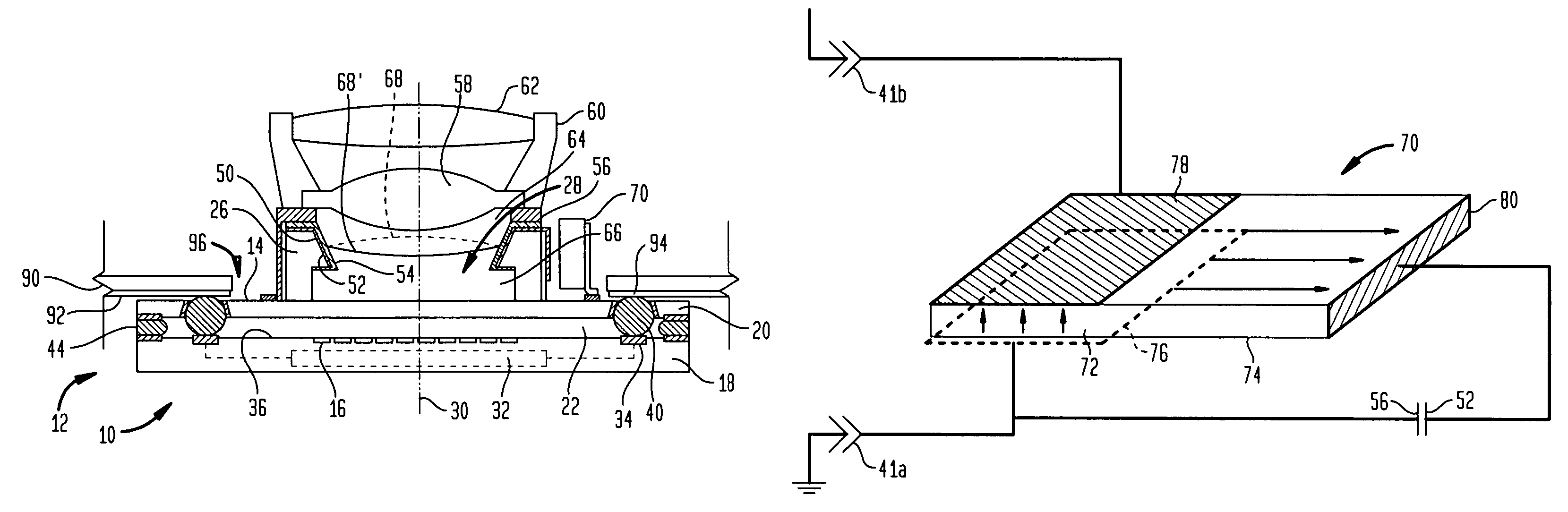
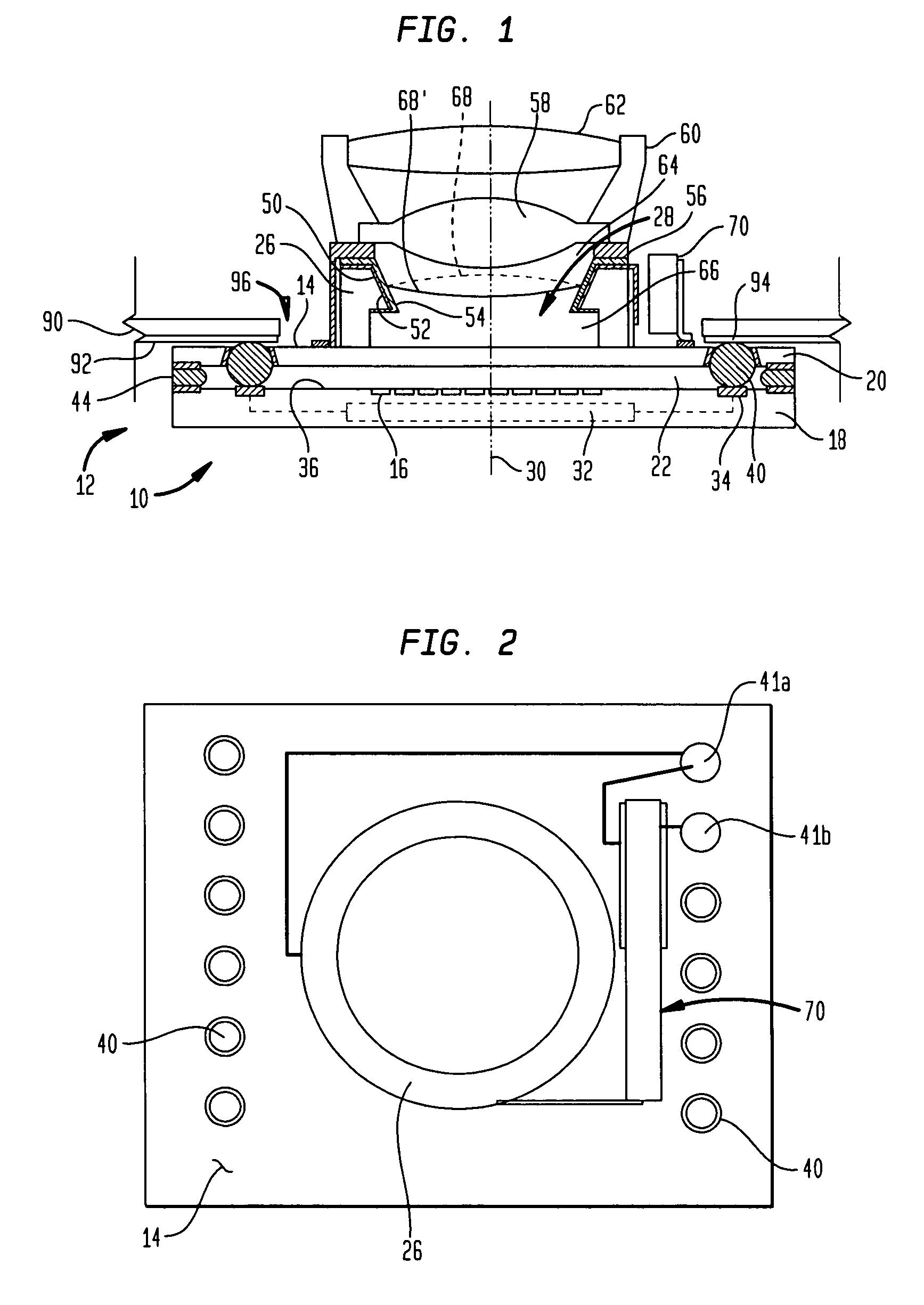
[0021]A camera module 10 (FIG. 1) according to one embodiment of the invention includes an optoelectronic sensor 12. The sensor has a body which includes a front surface 14 and an array of optically sensitive elements 16 such as CCD imaging cells arranged so that light impinging on the front surface 14 will pass to these optically sensitive elements. In the particular embodiment depicted in FIG. 1, the sensor body includes a semiconductor chip 18 and a cover 20 which is transparent, at least in those regions aligned with optically sensitive elements 16. Cover 20 typically is formed from glass or a transparent polymer. Cover 20 has an inner surface 22 facing toward chip 18 and an outer surface facing away from the chip, this outer surface constituting the front surface 14 of the sensor. A structure including a generally cylindrical, tubular container wall 26 projects from the outer surface 24 of cover 20. Container wall 26 may be formed integrally with cover 20, or may be assembled t...


PUM


Abstract

An electronic camera module includes a lens or refractive element formed by a pair of immiscible liquids and having optical properties which can be varied by applying a voltage so as to deform the meniscus. One of the two liquids extends from the meniscus all the way to the front surface of the sensor, so that light passing through the meniscus does not encounter further changes in refractive index enroute to the sensor.

Description

BACKGROUND OF THE INVENTION[0001]The present invention relates to electronic cameras and to methods and intermediate structures useful in forming the same.[0002]An electronic camera module includes an optoelectronic sensor which includes an array of sensitive elements capable of converting light to electrical signals and optical elements for focusing an image of a scene to be captured onto the array. Most commonly, the sensor includes a semiconductor imaging chip incorporating charged coupled device (“CCD”) elements or other optically sensitive elements such as p-n junctions in a CMOS structure. Each element is capable of capturing one picture element or “pixel” of the image. The imaging chip typically also includes conventional circuitry for converting the signals from the elements into a stream of data representing the image. The sensor may include either an imaging chip alone or an imaging chip together with a transparent cover which protects the sensitive elements from dust part...

Claims


Application Information

Patent Timeline
Patent Type & Authority Patents(United States)
IPC IPC(8): G02B1/06
CPCG02B3/14G02B26/005H04N5/2254H04N5/2257H01L27/14618H04N23/57H04N23/55
Inventor HUMPSTON, GILES
Owner TESSERA INC
Why Eureka
Try Eureka