Flexible circuit board with heat sink

a flexible circuit board and heat sink technology, applied in the field of flexible circuit boards, can solve the problems of conventional flexible circuit boards that cannot stand the heat generated by the operation of high-power electronic components, conventional flexible circuit boards that have a higher heat dissipation rate are not suitable for flexibility applications, etc., and achieve the effect of suitable for high-power electronics applications

Inactive Publication Date: 2008-10-28
WALSIN LIHWA
View PDF12 Cites 40 Cited by
  • Summary
  • Abstract
  • Description
  • Claims
  • Application Information

AI Technical Summary

Benefits of technology

[0025]Based on the above, each of the abovementioned flexible substrate, circuit board and optoelectronic device provided in the present invention simultaneously has the flexibility and the heat dissipation ability, and is especially suitable for the high power electronics application.

Problems solved by technology

However, such a flexible circuit board usually cannot stand the heat generated from the operation of the high power electronic components mounted on the circuit board since the laminar structure of the circuit board can be delaminated due to the deformation of circuit board.
Therefore, the conventional flexible circuit board faces the problem for the application of the high power electronic.
Accordingly, the conventional circuit board with higher heat dissipation is not suitable for the flexibility application since the laminar structure can be damaged when the circuit board is bent.
However, the respective light paths projected from those high power LEDs 35′ will be almost perpendicular to the planar heat dissipation substrate 100′ since the planar heat dissipation substrate 100′ is not applicable for the flexible purpose.
However, although the latch structures 41′, 42′ can be used as a hinge for bending the LED array, it is obvious that the flexibility of such structure is still not good enough for many demanded applications.
Moreover, such optoelectronic device structure is also complicated and costly since many components should be assembled together.

Method used


Image

  • Flexible circuit board with heat sink
  • Flexible circuit board with heat sink
  • Flexible circuit board with heat sink

Examples


Embodiment Construction

[0031]The present invention will now be described more specifically with reference to the following embodiments. It is to be noted that the following descriptions of preferred embodiments of this invention are presented herein for purposes of illustration and description only; it is not intended to be exhaustive or to be limited to the precise form disclosed.

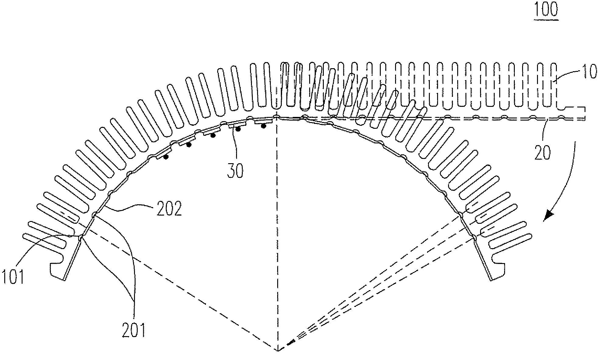
[0032]Please refer to FIG. 3, which shows a flexible heat dissipation substrate according to an embodiment of the present invention. The flexible heat dissipation substrate 100 includes a heat sink 10 and a heat spreader 20. For the flexibility purpose, a plurality of first and second grooves 101, 201 are formed on the respective upper surfaces of the heat sink 10 and the heat spreader 20, and the position of each of the first grooves 201 is corresponding to each of the second grooves 101, so as to provide an area for buffering the deformation of the substrate 100 when it is bent. In an alternative embodiment of the present inve...


PUM


Abstract

A novel flexible circuit board with heat dissipation ability is provided. The flexible circuit board includes a heat sink and a heat spreader having at least one circuit substrate mounted thereon. The heat spreader has a first lower surface and a first upper surface which has a plurality of first grooves formed thereon. At least one platform is formed between two adjacent ones of the first grooves for mounting the at least one circuit substrate. The heat sink has a second lower surface and a second upper surface which has a plurality of second grooves formed thereon and is connected to the first lower surface.

Description

FIELD OF THE INVENTION[0001]The present invention relates to a flexible circuit board, and in particular to a flexible circuit board having a heat sink bonded therewith.BACKGROUND OF THE INVENTION[0002]Due to the rapid developments of the information applications (IA) platform and the communication system as well as the development of the consumer electronics toward the trend of the “light-weight, thin, short and small” design, the development of the flexible circuit board (soft circuit board) is becoming more and more important. The conventional flexible circuit board is typically formed by a plastic substrate coated with copper foil. However, such a flexible circuit board usually cannot stand the heat generated from the operation of the high power electronic components mounted on the circuit board since the laminar structure of the circuit board can be delaminated due to the deformation of circuit board. Therefore, the conventional flexible circuit board faces the problem for the ...

Claims


Application Information

Patent Timeline
Patent Type & Authority Patents(United States)
IPC IPC(8): H05K7/20H01L23/36
CPCF21K9/00F21V29/2212F21V29/85H05K7/205F21V29/777F21V29/80F21Y2101/02H05K1/189F21Y2115/10F21V29/89
Inventor HAN, WEI-KUOTAIN, RA-MIN
Owner WALSIN LIHWA
Why Eureka
Try Eureka