Brush seal

Inactive Publication Date: 2008-11-04
MTU AERO ENGINES GMBH
View PDF38 Cites 32 Cited by
  • Summary
  • Abstract
  • Description
  • Claims
  • Application Information

AI Technical Summary

Benefits of technology

[0009]The first positioning arrangement may be configured as at least one weld spot which projects beyond the circumferential surface of the bristle housing and engages in a recess, correspondingly designed as second positioning arrangement, on the stator or rotor for the defined, anti-rotation positioning of the brush seal. A welding process having low generation of heat is used to avoid deformation of the plates.
[0010]Such a projection in the form of a weld spot extends circumferentially only over a short section and

Problems solved by technology

On account of the set bristles, reliable functioning in the event of incorrect installation of the brush seal, i.e., the brush seal is inserted in the incorrect orientation into its seat on the stator or rotor and the bristles are set against the direction of rotation of the rotor, is not ensured, since the bristles can partly bend to a considerable extent.
The press fit may prove to be critical with regard to the material loads, in particular in the case of large external dimensions of the bristle housing.
Due to first and second positioning arrangements, interacting in a positive-locking manner, for positioning the bristle housing in a seat on the stator, such as,

Method used


Image

  • Brush seal
  • Brush seal
  • Brush seal

Examples


Embodiment Construction

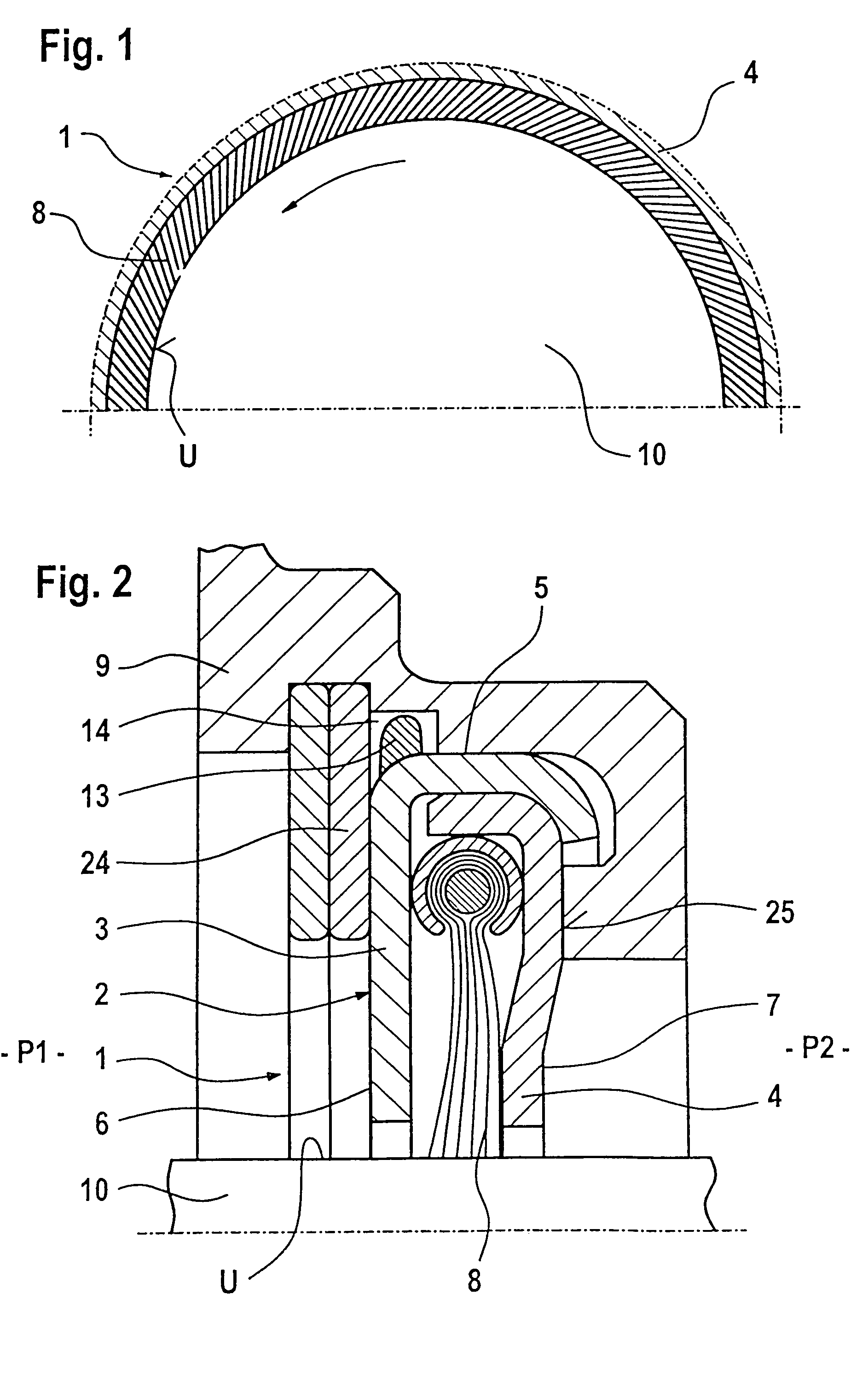
[0021]FIG. 1 is a plan view of a cutaway portion of a brush seal 1, this cutaway portion being restricted to the essential parts for illustrating the bristles 8 set in the direction of rotation of the rotor. FIG. 1 illustrates a section of a supporting plate 4 which forms a bristle housing 2 together with a cover plate 3. With their free ends, the bristles 8 touch a circumferential surface U of a rotor 10 and, starting from their clamping point, are set relative to the radial at an angle of between 40° and 50° in the direction of rotation of the rotor, which is identified by an arrow. In FIG. 1, the chain-dotted parting line extends in the radial direction. Due to the setting of the bristles 8, a smooth, radial deflection of the bristle stack upon contact with the rotor 10 is ensured. This arrangement results in low wear of the bristles 8 and also to a good sealing effect of the brush seal 1.

[0022]Due to the setting of the bristles 8, the brush seal 1 must not be fitted in any orien...


PUM

PropertyMeasurementUnit
Angleaaaaaaaaaa
Angleaaaaaaaaaa

Abstract

A brush seal for sealing a rotor with respect to a stator includes a bristle housing which is held on the stator or rotor, a cover plate, a supporting plate, a circumferential surface and two side surfaces and in which bristles oriented with their free ends to the rotor or stator are fastened. The bristle housing, for ensuring correct, anti-rotation installation in its seat, includes a first positioning arrangement on at least one side surface or the circumferential surface, the first positioning arrangement interacting in a positive-locking manner with a correspondingly configured second positioning arrangement on the stator or rotor or a separate fastening element for the definite positioning of the bristle housing.

Description

FIELD OF THE INVENTION[0001]The present invention relates to a brush seal for sealing a rotor with respect to a stator. The brush seal includes a bristle housing which is held on the stator or rotor, a cover plate, a supporting plate, a circumferential surface and two side surfaces and in which bristles oriented with their free ends to the rotor or stator are fastened.BACKGROUND INFORMATION[0002]In conventional brush seals, the free ends of the bristles fastened in a bristle housing having a cover plate and a supporting plate extend against a sealing surface of the rotor or stator and thus seal off the annular gap between rotor and stator. With a good sealing effect and in a conventional arrangement, axial construction space can be saved with such brush seals compared with seals which can be used as an alternative, such as labyrinth seals, for example when used in stationary gas turbines or aircraft engines. The bristles of the brush seals can be set in the direction of rotation of ...

Claims


Application Information

Patent Timeline
IPC IPC(8): F16J15/44F16J15/32F16J15/22B21D39/00B21D53/84B23K9/00B23K9/007F16J15/3288
CPCF16J15/3288Y10T403/1691
Inventor GAIL, ALFONSPRINS, LODEWIJKWERNER, KLEMENS
Owner MTU AERO ENGINES GMBH
Why Eureka
Try Eureka