
Device for proactive modulation of cardiac strain patterns

a technology of proactive modulation and cardiac strain, which is applied in the field of direct cardiac compression devices, can solve the problems of known attempts to proactively modulate, dccds do not proactively modulate, and the supply of donor hearts is not adequate to meet demand, so as to reduce the apoptosis of the myocardium

Active Publication Date: 2008-11-04
TEXAS A&M UNIVERSITY
View PDF18 Cites 18 Cited by
  • Summary
  • Abstract
  • Description
  • Claims
  • Application Information

AI Technical Summary

Benefits of technology

The device promotes beneficial growth and remodeling of the myocardium, reduces apoptosis, and supports ventricular recovery by restoring a physiological strain pattern, potentially enhancing heart function and preventing complications like ventricular rupture.

Problems solved by technology

Heart transplant is available for some patients with the most severe heart failure, however the supply of donor hearts is not adequate to meet demand and there are many complications associated with immunosuppression.
Despite the promise shown by growth and remodeling of damaged or diseased heart tissue, there have been no known attempts to proactively modulate the strain pattern during contraction.
Yet current DCCDs do not proactively modulate the strain pattern so as to guide heart recovery and / or myocardial recovery.
In contrast, many devices may cause detrimental remodeling and / or apoptosis because the induced strain pattern is so grossly abnormal.
Thus, the fact that prior DCCDs have tried to fit well the diastolic configuration is inconsequential to achieving an appropriate contraction strain pattern because their end-systolic configurations are either grossly aberrant or unknown.
Nevertheless, it is uncertain what the systolic configuration is for these devices because it is not disclosed.
Upon doing a force balance, however, one realizes that the Hewson embodiment 1 is unrealistic and not implantable.
However, all current operable DCCDs suffer from a tendency to increase or even invert the curvature of the heart and thus produce an aberrant strain pattern during contraction.

Method used


Image

  • Device for proactive modulation of cardiac strain patterns
  • Device for proactive modulation of cardiac strain patterns
  • Device for proactive modulation of cardiac strain patterns

Examples


example 1

Formation of a Prototype DCCD

[0061]A prototype of one embodiment of the present invention was built to fit a 110 kg bovine into which the device was implanted for an acute period (2 hours) to test the valve plane attachment and the preservation of cardiac curvature during assist with varying degrees of heart failure which was induced pharmacologically with high doses of a beta-blocker. Because the period of implantation was brief, biocompatible materials were not utilized; rather inexpensive and readily available materials were used. The methods of construction and sizing are directly applicable to devices for use in humans or other animals.

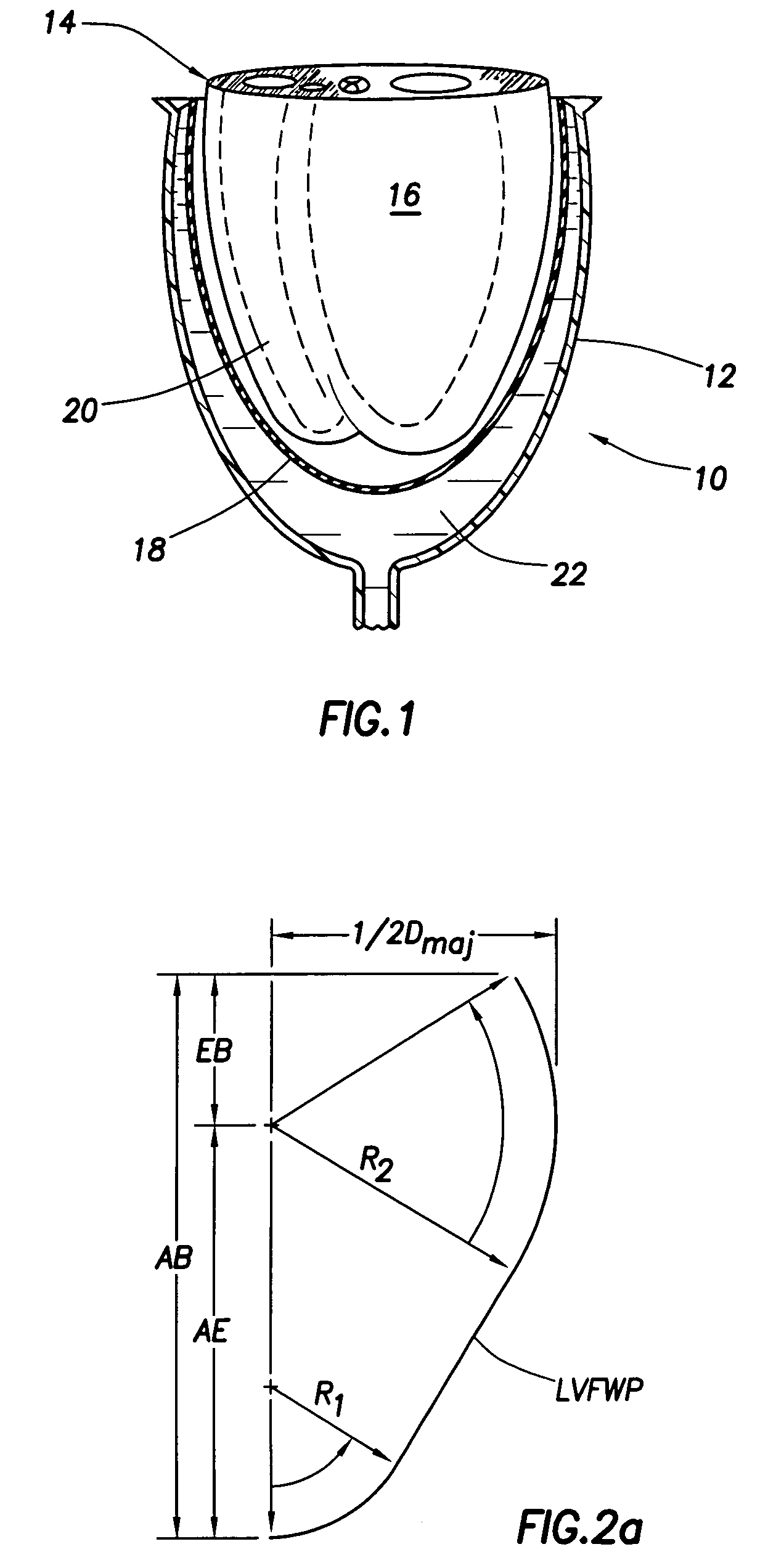
[0062]The size of this device was determined by 5 cardiac measurements—all of which can be made via a cardiac ultrasound. The major diameter (Dmaj) and minor diameter (Dmin) were obtained from a short axis view in the equatorial region. From a long axis view one can obtain: AB-distance from apex to base; EB-distance from equator (fattest part) to...

example 2

Attachment of a DCCD to the Heart

[0067]Various methods of attaching the device to the heart have been tested using the fixed heart that was measured in order to determine the size of the device. As shown in FIG. 3, the heart was sewn to the device with running sutures that go completely around the heart. Although this is more laborious than a vacuum attachment method, other DCCDs require the device boundaries to be sutured to the heart and so a similar approach was tried here.

[0068]For animal models of CHF, the attachment in FIG. 3 is likely to be acceptable. Yet in CHF patients, such a method of attachment would be prone to surgical complications because there is too much pericardial fat and because of the need to sew near important vascular structures (e.g. left and right coronary arteries, great cardiac vein and coronary sinus). Moreover, the coronary sinus and right coronary arteries are on the posterior side of the heart, an area with limited exposure in-vivo.

[0069]To reduce th...

example 3

Use of a DCCD

[0071]Experiments were performed using a device with an outer shell similar to that of the Hewson patent containing a plexiglass window in the outer shell to allow observation of the cardiac curvatures with a CCD camera while the device was in operation. The Hewson device was designed to be held in place by contact forces between the rim and the heart, but even active hearts are soft tissues that can undergo high shear and squeeze out of the device. Specifically, the myocardium of hearts are organized into sheets that allow contracting myocytes to rearrange and shear to attain high radial motions.

[0072]Thus when the DCCD similar to the Hewson device was implanted in a young bovine, even with a normal contractility, the heart readily escaped the device. Accordingly, the Hewson device, as described in the Herson patent, appears to be inoperable and required serious modification of the device and / or its means of attachment in order to develop an operable device.

[0073]Speci...


PUM


Abstract

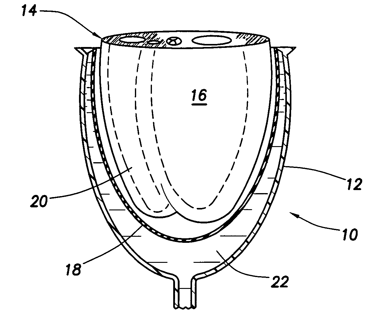
A direct cardiac assist device which may aid in ventricular recovery. The device proactively modulates cardiac strain pattern to produce a contraction strain pattern that induces beneficial growth and remodeling of the myocardium or prevents or reduces apoptosis of the myocytes. The device may include an outer shell. membrane, or mesh and an inner membrane. The space between the outer member and the membrane may be filled with fluid that is pressurized during contraction. The device prescribes a beneficial strain pattern during heart contraction. This strain pattern does not invert the curvatures or grossly alter the curvatures of the heart and may assist in myocyte regrowth and healing of the failing heart.

Description

PRIORITY CLAIM[0001]The present application claims priority under 35 U.S.C. §119(e) to U.S. Provisional Patent Application Ser. No. 60 / 479,625 filed Jun. 18, 2003.TECHNICAL FIELD[0002]The present invention is related in general to a direct cardiac compression device. In particular is a direct cardiac compression device that proactively modulates the strain pattern in the heart during contraction so as to reduce apoptosis in the myocardium and / or induce beneficial growth and remodeling of the myocardium and / or scarred regions. In particular, the device of the present invention does not invert or grossly perturb the curvature of the hear during contraction. In so doing this invention may promote recovery of the heart from injury, ischemia, infarction, infection, and / or congestive heart failure; and when combined with pharmacotherapy, pacing, electrical resynchronization, surgical reconstruction, stem cell therapy, gene therapy, and / or other therapies, it may further enhance recovery o...

Claims


Application Information

Patent Timeline
Patent Type & Authority Patents(United States)
IPC IPC(8): A61N1/362A61F2/00A61M1/10
CPCA61F2/2481A61M1/1068A61M60/289A61M60/191A61M60/468A61M60/861
Inventor CRISCIONE, JOHN C.
Owner TEXAS A&M UNIVERSITY
Learn More