Eureka AIR delivers breakthrough ideas for toughest innovation challenges, trusted by R&D personnel around the world.

Gas concentration detecting apparatus

Inactive Publication Date: 2008-11-04
DENSO CORP
View PDF7 Cites 7 Cited by
  • Summary
  • Abstract
  • Description
  • Claims
  • Application Information

AI Technical Summary

Benefits of technology

[0008]The present invention was accomplished in light of the abovementioned circumstances. An object of the present invention is to provide a gas concentration detecting apparatus that is able to suitably detect abnormality in relation to various circuits incorporated in the apparatus, without causing the configuration of the apparatus to be more complicated.
[0010]Hence, during the calculation of the element resistance, no change of the element current responds to the change added to the applied voltage on the sensor element so that no change of the element current can be monitored, for example, if any abnormality occurs in the sensor control system, such as the power supply short circuit or the GND short circuit at one or more of the positive and negative terminals of the sensor element, or the terminal-to-terminal short circuit across the positive and negative terminals. If the change is added to the element current instead of the applied voltage, no change of the applied voltage will respond to the change of the current so that no change of the applied voltage can be monitored. By determining whether no change of current or voltage responds to the change of the applied voltage or current, therefore, one method for abnormality detection can suitably detect the abnormality in the sensor control system, such as the power supply short circuit, the GND short circuit, the terminal-to-terminal short circuit, or the disconnection. The above-described abnormality detection method detects the abnormality with the measured data (current variation, or voltage variation) for use in the element resistance calculation. No additional A / D converter (A / D input for the microcomputer) is thus needed for the abnormality detection, thereby preventing the need for using a complicated configuration.
[0011]One technique for calculating the element resistance with the change added to the applied voltage or current of the sensor element is an element resistance calculation method by the so-called sweeping method. This method calculates the element resistance based on the variation of the current or voltage caused by temporally changing the applied voltage or current of the sensor element. It is known that this calculation method needs no modification of the applied voltage on the sensor into the resistance-dominant region of a V-I characteristics, thereby reducing the no-detection time of the gas concentration. The applied voltage or current of the sensor element can also be alternately or continuously changed to add change to that applied voltage or current. The element resistance can also be calculated as element admittance in addition to the element impedance. The admittance is the inverse of the element impedance.

Problems solved by technology

This configuration is very complicated.
The above-described abnormality detection method in the Japanese application patent laid-open publication, however, determines the state where the sensor element should obviously be activated and detects the sensor element abnormality if the sensor element is not activated under the state.
This then places much restriction on the sensor element abnormality detection.
This makes it hard to simplify the configuration.

Method used


Image

  • Gas concentration detecting apparatus
  • Gas concentration detecting apparatus
  • Gas concentration detecting apparatus

Examples


first embodiment

[0036]Referring to FIGS. 1 to 6, a first embodiment of the present embodiment will now be described.

[0037]In the present embodiment, an air-fuel ratio detecting apparatus is embodied, which takes in an exhaust gas (combustion gas) released from a vehicle engine as a detected gas and detects oxygen concentration (air-fuel ratio, hereinafter also referred to as A / F) in the gas. The air-fuel ratio control system including an engine ECU or the like uses the detection results of the air-fuel ratio. The air-fuel ratio control system adequately uses combustion controls such as a stoichiometry combustion control for feedback controlling the air-fuel ratio near the stoichiometry and a lean combustion control for feedback controlling the air-fuel ratio in a predetermined lean area.

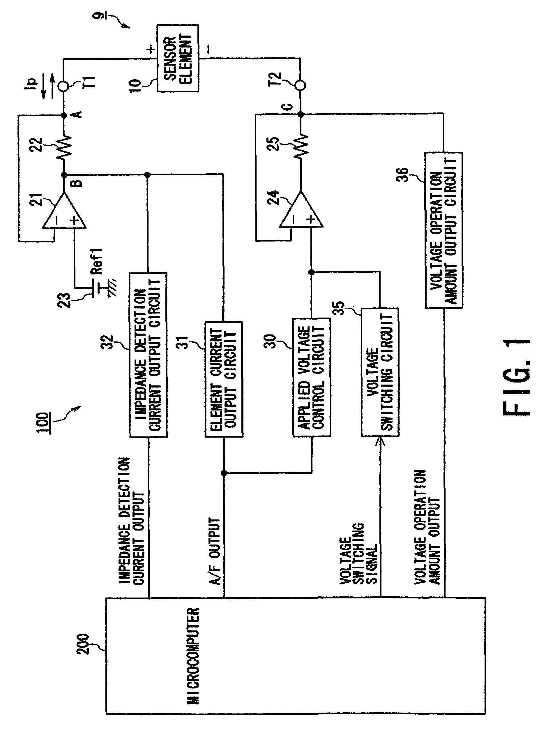
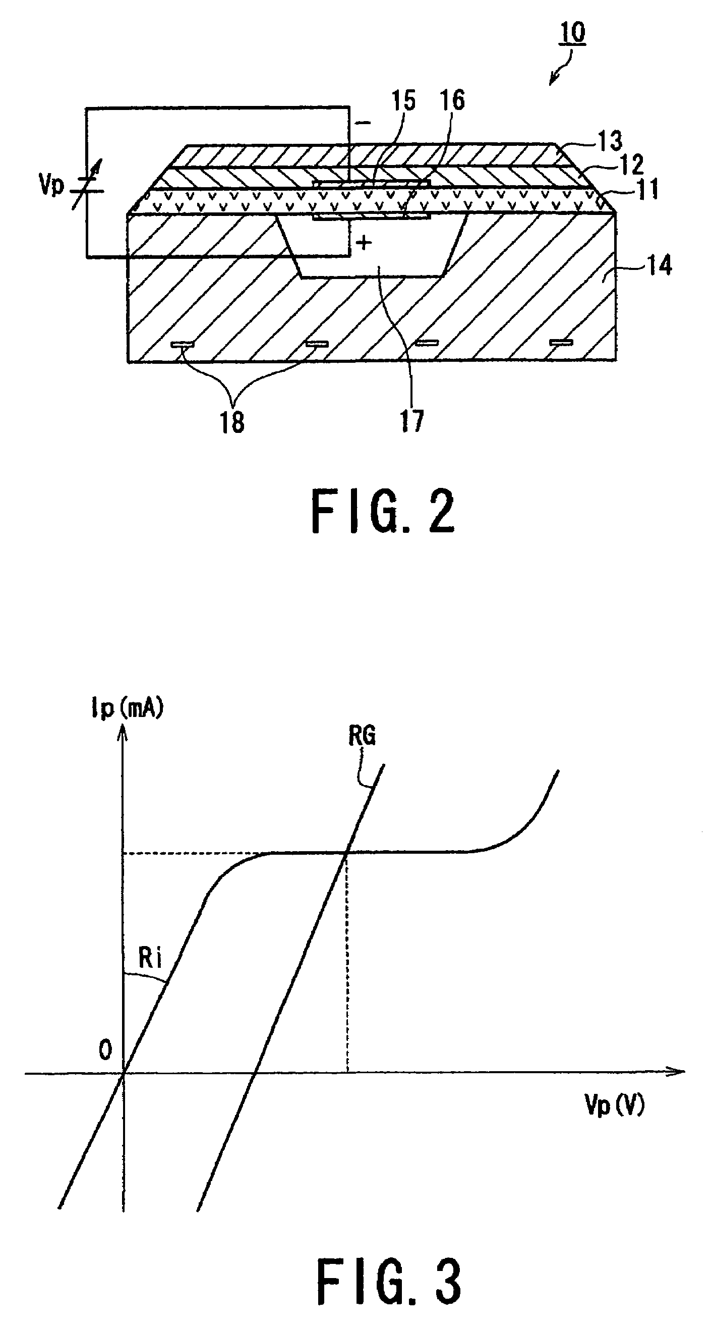
[0038]FIG. 1 shows the configuration of the air-fuel ratio detecting apparatus including a sensor control circuit, while FIG. 2 shows the configuration of the A / F sensor.

[0039]First, with reference to FIG. 2, the A / ...

second embodiment

[0062]Referring to FIGS. 7 and 8, a second embodiment of the present invention will now be described.

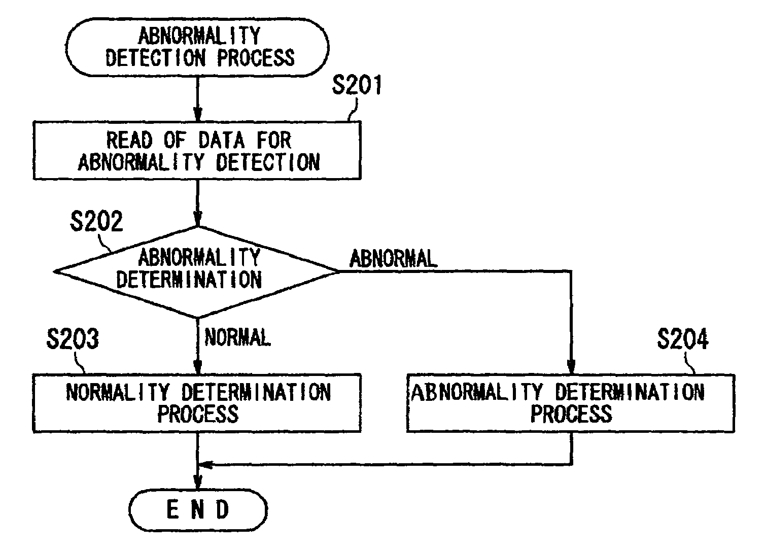
[0063]The second embodiment according to the present invention will now be described, with an emphasis on the differences from the above-described first embodiment. The first embodiment uses as the data for abnormality detection the current variation ΔI (impedance detection current output) responding to the switching of the applied voltage to the sensor.

[0064]In contrast, the second embodiment uses the calculated value of the element admittance (element admittance=ΔI / ΔV) as the data for abnormality detection. In short, no current responds to the applied voltage change, or no normal calculated value of the element admittance is provided, during the detection of the element admittance, if any abnormality occurs in the sensor control system, such as the power supply short circuit or the GND short circuit at at least one of the + and − terminals of the sensor element 10, or the terminal-...


PUM


Abstract

In a gas concentration detecting apparatus, a voltage is applied to electrodes of a sensor element. A change is caused in either the applied voltage or an element current. An amount of a change in each of a current value and a voltage value caused is measured in response to the caused change. An amount of resistance of the sensor element is calculated based on a ratio between the change amounts in the current value and the voltage value. A detection unit detects abnormality relating to controlling the sensor by utilizing at least one of the change amounts in the current value and the voltage value.

Description

BACKGROUND OF THE INVENTION[0001]1. Field of the Invention[0002]The present invention relates to a gas concentration detecting apparatus for detecting a specific component concentration based on detection results from a gas concentration sensor and, more particularly, to an improved technique for suitably detecting abnormality in a sensor control system.[0003]2. Description of the Related Art[0004]One known gas concentration sensor is, for example, a limiting-current type air-fuel ratio sensor (referred to as A / F sensor), which takes an exhaust gas released from a vehicle engine as a detected gas and detects the oxygen concentration (air-fuel ratio) in the exhaust gas. Specifically, the A / F sensor has a sensor element that includes a solid electrolyte member and a pair of electrodes disposed on that solid electrolyte member. The A / F sensor is configured to flow an element current corresponding to the present concentration, which is caused by an applied voltage on the sensor element....

Claims


Application Information

Patent Timeline
IPC IPC(8): G01N27/409G01N27/41G01N27/26G01N27/407G01N27/416G01N27/417G01N27/419
CPCG01N27/4071
Inventor HADA, SATOSHIKAWASE, TOMOOKUROKAWA, EIICHI
Owner DENSO CORP
Why Eureka
Eureka Blog
Learn More