Stray light insensitive detector system and amplifier

a detector system and amplifier technology, applied in electromagnetic transmission, electromagnetic transmission, semiconductor lasers, etc., can solve the problems affecting the detection of signals, and stray light, so as to achieve the effect of increasing the noise floor of the system

Inactive Publication Date: 2008-11-11
EXCELITAS TECH
View PDF8 Cites 0 Cited by
  • Summary
  • Abstract
  • Description
  • Claims
  • Application Information

AI Technical Summary

Benefits of technology

[0003]One problem that arises when handling multiple optical signals in the same package concerns stray light. For example, in the case of optical performance monitoring system, the detector is located within the hermetic package in order to detect the light that is filtered by the tunable filter. The stray light, however, may be present in the module from the reference source or light that is rejected by the tunable filter as being outside its current passband. This stray light can have the effect of increasing the noise floor of the system or otherwise impairing detection of the signal of interest since it can also be detected by the detector after reflections within the package. In the case of an amplifier system, it can be difficult to detect the input signal, especially before amplification when there may be light in the hermetic package, such as stray pump light.

Problems solved by technology

One problem that arises when handling multiple optical signals in the same package concerns stray light.
The stray light, however, may be present in the module from the reference source or light that is rejected by the tunable filter as being outside its current passband.
This stray light can have the effect of increasing the noise floor of the system or otherwise impairing detection of the signal of interest since it can also be detected by the detector after reflections within the package.
In the case of an amplifier system, it can be difficult to detect the input signal, especially before amplification when there may be light in the hermetic package, such as stray pump light.

Method used


Image

  • Stray light insensitive detector system and amplifier
  • Stray light insensitive detector system and amplifier
  • Stray light insensitive detector system and amplifier

Examples


Embodiment Construction

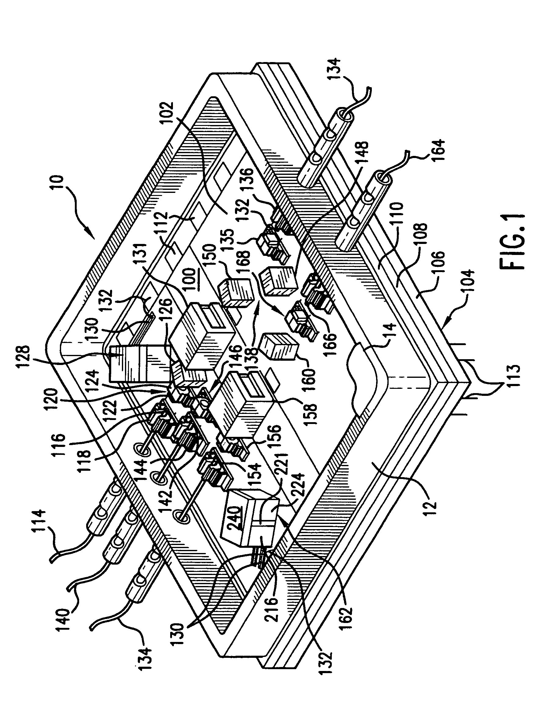
[0018]FIG. 1 shows a two-stage amplifier module 10, which has been constructed according to the principles of the present invention.

[0019]The module 10 comprises an optical bench 100. In the present invention, the optical bench 100 is fabricated from aluminum nitride. It has a metal coating 102 to function as an adhesion layer. In the present invention, the adhesion metal includes gold.

[0020]The optical bench 100 is attached to a module base 104. Presently, this base 104 is fabricated from a multi-layer silica composite substrate. Specifically, the base comprises a lower layer 106, an intermediate layer 108, and a top layer 110. The top layer 110 of the base 104 is the layer to which the bench 100 is bonded.

[0021]Wire bond pads 112 are deposited on the top layer 110 of the base 104. Wire jumpers 132 are provided between these bond pads or wire bonding areas 112 and the active components installed on the bench 100 or metal bench traces 130 formed in the metal layer 102. The middle an...


PUM


Abstract

A detector system for a fiber optic component is insensitive to stray light. Specifically, the invention comprises a detector chip, which converts received light into an electric signal. A baffle substrate is positioned over the detector chip. This baffle substrate has a transmission port through which an optical signal is transmitted to the detector chip. As a result, light that is not directed to be transmitted through the port is blocked by the baffle substrate. In this way, it rejects stray light that may be present in the hermetic package. A detector substrate is provided on which the detector chip is mounted. This detector substrate preferably comprises electrical traces to which the detector chip is electrically connected. The detector substrate can further comprise bond pads for wire bonding to make electrical connections to the electrical traces.

Description

BACKGROUND OF THE INVENTION[0001]Monitoring detectors are used in many fiber-optic components. For example, detectors are typically located in diode laser modules to detect light from the front or rear facets in order to monitor the diode laser's output. They can also be used in fiber amplification systems to detect the optical signals before and after amplification. In still another example, they can be used in monitoring systems to detect the light transmitted through a tunable filter.[0002]Presently, hybrid-integrated optical systems are being manufactured that offer higher levels of integration. For example, in one example, a reference source, tunable filter, and detectors are located in a single hermetic package. In another example, two-stage amplifier modules have been designed. In both of these examples, multiple optical signals are being handled within the same hermetic package.SUMMARY OF THE INVENTION[0003]One problem that arises when handling multiple optical signals in th...

Claims


Application Information

Patent Timeline
Patent Type & Authority Patents(United States)
IPC IPC(8): H04B10/06H01S5/022
CPCH01S5/02216H01S5/02248H01S5/02284H01S5/0683H01S5/02251H01S5/02325
Inventor FLANDERS, DALE C.ATIA, WALIDFITCH, ERIC E.LE, MINH VANMURDZA, RANDAL A.PAYER, ROBERT L.KORN, JEFFREY A.WANG, XIAOMEIBUCHWALD, WALTER R.NEWMAN, III, L. JAMES
Owner EXCELITAS TECH
Why Eureka
Try Eureka