
Multi-shell air intake manifold with passage for map sensor and method of producing same

a technology of map sensor and air intake manifold, which is applied in the direction of air intake for fuel, combustion air/fuel air treatment, machines/engines, etc., can solve the problems of easy breakage of pins, high tooling cost of such molding tools, and easy maintenance of pins, so as to reduce tooling cost, reduce tooling cost, and facilitate manufacturing

Inactive Publication Date: 2008-11-18
MANN HUMMEL GMBH
View PDF24 Cites 26 Cited by
  • Summary
  • Abstract
  • Description
  • Claims
  • Application Information

AI Technical Summary

Benefits of technology

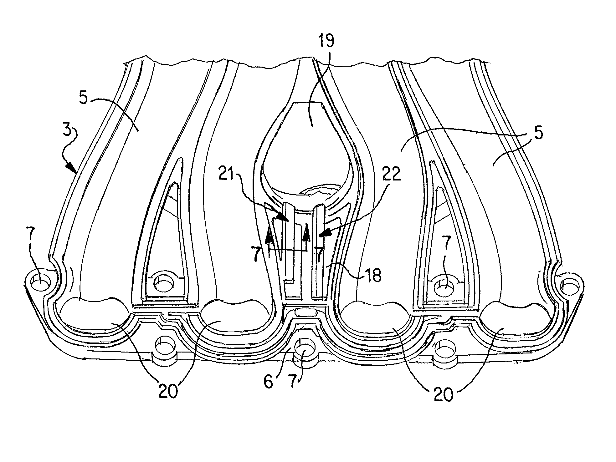
[0005]In accordance with the invention, at least one passage for a MAP sensor or purge gas introduction is constructed between the upper and middle shells of an intake manifold constructed of a plurality of molded synthetic resin shells. The passage may be constructed by a groove in either the upper shell or in the middle shell or by registering grooves in both the upper and middle shells so that part of the passage is in the upper shell and part in the middle shell. By designing the passage so that it is formed between the shells, it is possible to create a passage without the use of a pin. Also, by creating the passage in this manner, the placement of the MAP sensor and purge gas connector is less restricted, and it becomes possible to locate them in more convenient locations.
[0006]The present invention uses two mating shells with an open groove in the facing surface of at least one of the shells to create a passageway. The mating shells are vibration or friction welded to each other to form the passageway between them. Advantages of the invention include (1) easier manufacturing, (2) the location of the MAP and purge connections is less limited, and (3) decreased tooling cost. The invention can be used with any synthetic resin intake manifold formed from a plurality of molded shells assembled to each other.
[0007]It is particularly advantageous if the groove is oriented substantially perpendicular to the line of draw of the mold in which the shell is formed. This eliminates undercuts and facilitates opening of the mold and ejection of the molded manifold section. As used herein, the term “line of draw” refers to an imaginary line which indicates the direction in which the mold is opened.

Problems solved by technology

Production of such molding tools involves high tooling costs.
Also, the pin is a very high maintenance due to wear of the tool, and if the passage is long, it makes the pin easier to break.

Method used


Image

  • Multi-shell air intake manifold with passage for map sensor and method of producing same
  • Multi-shell air intake manifold with passage for map sensor and method of producing same
  • Multi-shell air intake manifold with passage for map sensor and method of producing same

Examples


Embodiment Construction

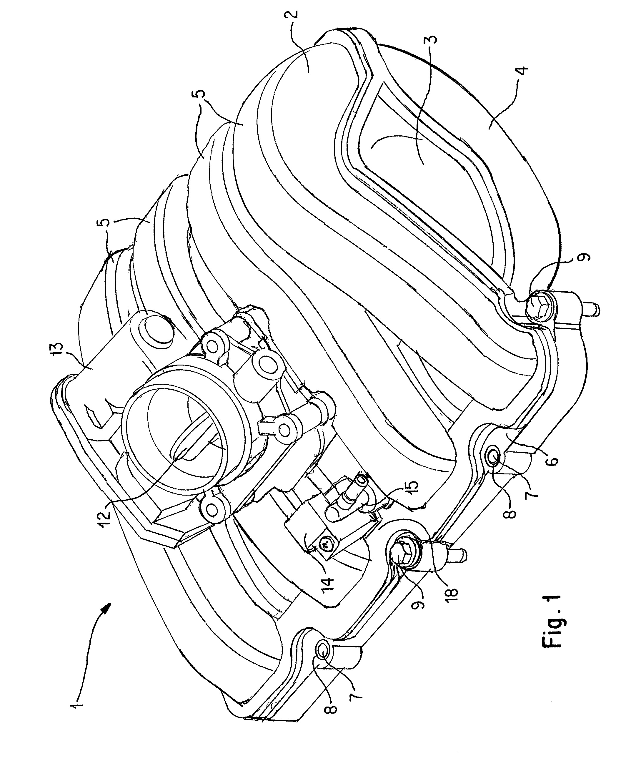
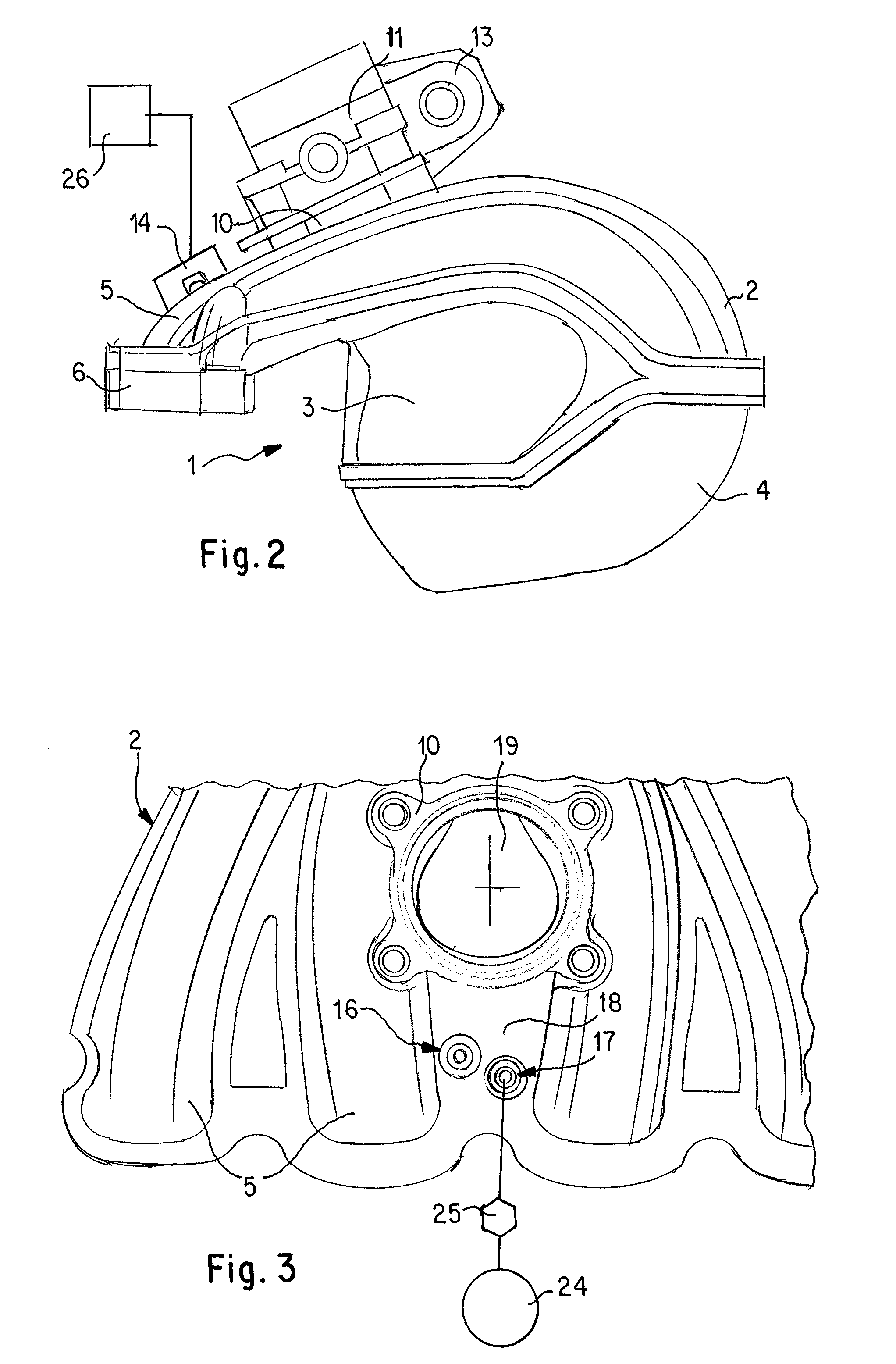
[0017]FIGS. 1 and 2 show an internal combustion engine air intake manifold 1 according to the present invention, which comprises an assembly of an upper shell 2, a middle shell 3 and a lower shell 4 of molded synthetic resin material. The assembled upper and middle shells define a plurality of individual inlet channels 5 which lead from an internal plenum chamber to inlets of cylinders of the engine. The inlet channels 5 terminate at a mounting flange 6, which can be fastened to the cylinder head of an internal combustion engine by mounting bolts 9 extended through mounting bolt holes 7 in flange 6. Mounting holes 7 may be provided with reinforcing bushings 8. A throttle body 11, comprising a throttle flap valve 12 and a throttle controller 13, is mounted on a throttle body mount 10 on top of upper shell 2.

[0018]Mounted on top of the manifold assembly 1 is a MAP sensor 14, which is connected to an engine control module 26 and serves to detect the manifold air pressure and transmits ...


PUM

PropertyMeasurementUnit
Diameteraaaaaaaaaa
Diameteraaaaaaaaaa
Massaaaaaaaaaa

Abstract

An air intake manifold assembly for an internal combustion engine composed of a plurality of molded synthetic resin shells assembled to each other so as to define a plenum chamber, a plurality of inlet channels leading from said plenum chamber to cylinder inlets of the internal combustion engine, and a throttle body passageway leading from a throttle body mount into the plenum chamber; with a groove formed in a surface of at least one of the shells facing an adjacent shell and extending from an inlet opening to the throttle body passageway or the plenum chamber so as to form an elongate passage between the assembled shells leading from the inlet to the throttle body passage or plenum chamber, and a method of forming such an intake manifold assembly.

Description

BACKGROUND OF THE INVENTION[0001]Light weight and durable intake manifolds for internal combustion engines can be constructed of moldable thermoplastic synthetic resin material. Such intake manifolds may be constructed of a plurality of molded sections or shells which are joined together, for example, by vibration welding, friction welding or sonic welding. Typically, such intake manifolds are made up of three sections: an upper shell, a middle shell and a lower shell. A plenum chamber is formed between the middle and lower shells, and a plurality of intake channels which lead to the individual cylinders of the engine are formed between the upper and middle shells.[0002]Intake manifolds require inlet openings for attached sensors such as a manifold absolute pressure sensor (MAP sensor) and / or introduction of secondary gases such as purge gases from an evaporative emission control system into the manifold. The MAP sensor provides manifold pressure information to a fuel injected engin...

Claims


Application Information

Patent Timeline
IPC IPC(8): F02M35/10
CPCF02M25/089F02M35/10032F02M35/10144F02M35/10222F02M35/10321F02M35/10354F02M35/1038F02M35/112F02D9/1035F02D2200/0406
Inventor VICHINSKY, KEVINHUFF, DAN
Owner MANN HUMMEL GMBH
Learn More