
Digital to analog converter and source driver

a digital to analog converter and source driver technology, applied in the field of digital to analog converters, can solve the problems of parasitic capacitance and adverse effects on the output of the dac, and achieve the effect of reducing the output error of the digital to analog converter and mitigating the effects of parasitic capacitan

Inactive Publication Date: 2008-11-18
SAMSUNG ELECTRONICS CO LTD
View PDF21 Cites 11 Cited by
  • Summary
  • Abstract
  • Description
  • Claims
  • Application Information

AI Technical Summary

Benefits of technology

The proposed solution effectively reduces output errors caused by parasitic capacitance, improving the analog quality of the output signal and enhancing the performance of DACs, particularly in applications like Liquid Crystal Displays.

Problems solved by technology

Unfortunately, analog signals can not be manipulated by digital computational systems.
While offering significant design and performance benefits, this approach suffers from the presence of a parasitic capacitance at the input terminal of the Op-Amp.
This parasitic capacitance has an adverse effect on the output of the DAC when modulating a voltage level of a non-inverting input terminal of the Op-Amp.

Method used


Image

  • Digital to analog converter and source driver
  • Digital to analog converter and source driver
  • Digital to analog converter and source driver

Examples


Embodiment Construction

[0019]The present invention will be described in the context of several exemplary embodiments shown in the accompanying drawings. The invention may, however, be variously embodied and should not be construed as being limited to only the illustrated embodiments.

[0020]In the present invention, a digital-to-analog converter (DAC) block receives a digital signal and converts it to a corresponding analog signal. The analog signal may then be output to an external circuit, such as a display apparatus.

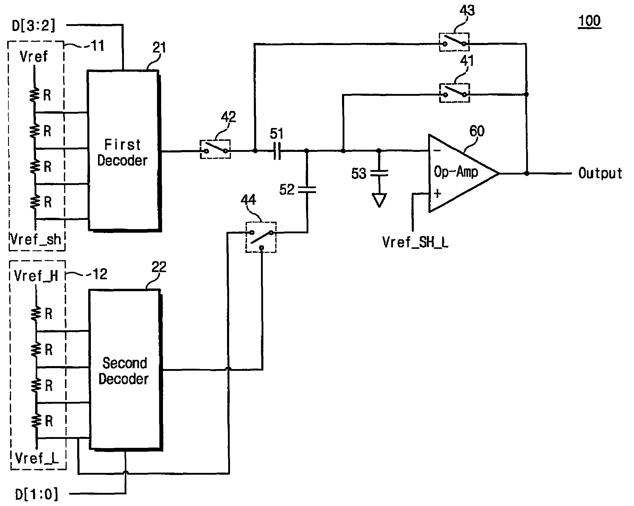
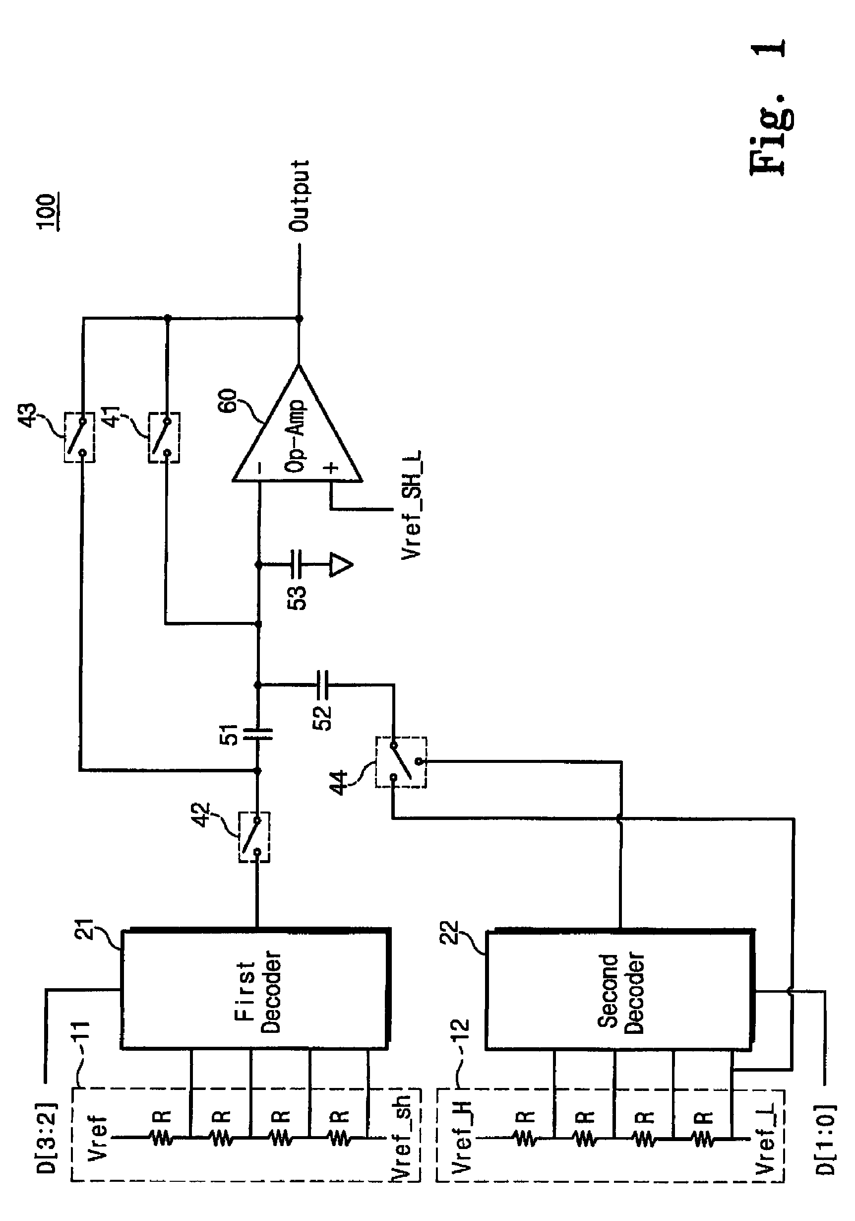
[0021]FIG. 1 is a block diagram illustrating a DAC according to an embodiment of the invention. DAC 100 of FIG. 1 has a modified structure of an R-type DAC. Referring to FIG. 1, the effects of a parasitic capacitor 53 apparent in the DAC may be cut off by connecting the non-inverting terminal of an operational amplifier (Op-Amp) 60 to a fifth reference voltage Vref_SH_L, and by connecting a first capacitor 51 and second capacitor 52 in the illustrated manner.

[0022]A first reference voltage (“...


PUM


Abstract

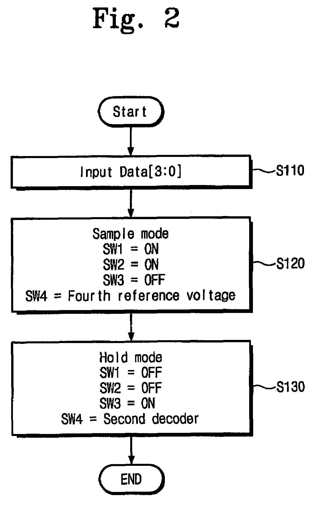
A digital to analog converter (DAC) converting digital data into a corresponding analog voltage is disclosed. The digital data includes upper bit data and lower bit data and the DAC includes; a first resistor circuit dividing first and second reference voltages to output a plurality of first division voltages, a first decoder selecting one of the first division voltages in response to the upper bit data, a second resistor circuit dividing third and fourth reference voltages to output a plurality of second division voltages, a second decoder selecting one of the second division voltages in response to the lower bit data, and a sample and hold circuit including a first capacitor and a second capacitor, and outputting the analog voltage in response to an output voltage from the first decoder and an output voltage from the second decoder, wherein the sample and hold circuit samples the output voltage of the first decoder during a sample mode, and adds the output voltages of the first and second decoders through the first and second capacitors to output a combined voltage during a hold mode.

Description

CROSS-REFERENCE TO RELATED APPLICATIONS[0001]This U.S. non-provisional patent application claims priority under 35 U.S.C. § 119 to Korean patent Application No. 10-2006-0073066 filed Aug. 2, 2006, the subject matter of which is hereby incorporated by reference.BACKGROUND OF THE INVENTION[0002]1. Field of the Invention[0003]The present invention relates to a digital to analog converter (DAC).[0004]2. Description of Related Art[0005]Most physical phenomena may be expressed as an analog value (or a varying analog signal) within a defined range of values. Temperature, pressure, voltage, current, light intensity, voice frequency, position, velocity, angular velocity, flow rate, etc., may all be expressed an analog signal having an instantaneous value at a point in time over a continuous range of possible values. Many analog ranges or scales may be used to accurately indicate the nature of the detected or measured phenomenon of interest.[0006]Unfortunately, analog signals can not be manip...

Claims


Application Information

Patent Timeline
Patent Type & Authority Patents(United States)
IPC IPC(8): H03M1/66
CPCH03M1/68H03M1/76H03M1/66
Inventor JEON, YONG-WEONJUNG, JI-WOONKO, JO-HYUN
Owner SAMSUNG ELECTRONICS CO LTD
Learn More