Device for the demounting of blades of a turbine or of a compressor

a turbine or compressor technology, applied in the direction of blade accessories, machines/engines, waterborne vessels, etc., can solve the problems of comparatively time-consuming and inability to push the last moving blad

Inactive Publication Date: 2008-11-25
SIEMENS AG
View PDF9 Cites 19 Cited by
  • Summary
  • Abstract
  • Description
  • Claims
  • Application Information

AI Technical Summary

Benefits of technology

[0007]An object on which the invention is based is to organize the procedure for the above described work of the maintenance, repair and renewal of blades in turbines more cost-effectively overall.
[0009]With such a device according to the invention, it is possible for the blades of turbines or compressors to be demounted in a comparatively short time on the associated blade wheel, without the associated rotor having to be destacked for this purpose. Furthermore, according to the invention, dispensing with destacking also makes the operation of reassembling the rotor unnecessary, so that, overall, considerable work time can be saved and costs can be lowered. According to the invention, in addition to the marked saving in terms of work time, the inspection time is also reduced considerably overall. Furthermore, a device for destacking the rotor may be dispensed with.
[0010]In the device according to the invention, its supporting means, with at least one bearing, is adapted to be brought to bear against a step of the blade wheel. Such a device can have a compact configuration and be used for various types of turbines or compressors, because it can have comparatively simple setting-up elements which can be provided with simple adjustment possibilities for adaption to different types of blade wheels.
[0011]Such a compact device can easily be handled by maintenance personnel when said work is being carried out.
[0013]A device is particularly advantageous in which the actuator means is designed with a tension element for engaging around the blade moving out of the wheel disk. Such a device is particularly easy to handle and is operationally reliable.
[0018]Furthermore, on the device according to the invention, a monitoring means should be provided, which is adapted for limiting the force acting on the blade by the actuator means. Such a monitoring means may be, for example, a load cell and a corresponding control and / or indicator for the actuator means. The monitoring means, in particular, prevents the situation where the groove formed on the wheel disk and receiving the blade root could be damaged during demounting.

Problems solved by technology

The demounting of such compressor moving blades must take place manually on account of the many different activities to be performed and is comparatively time-consuming.
Since the shrouds are of Z-shaped design, as seen in the radial direction, it is not possible for the last moving blade to be pushed axially into the otherwise fully equipped moving blade ring.

Method used


Image

  • Device for the demounting of blades of a turbine or of a compressor
  • Device for the demounting of blades of a turbine or of a compressor
  • Device for the demounting of blades of a turbine or of a compressor

Examples


Embodiment Construction

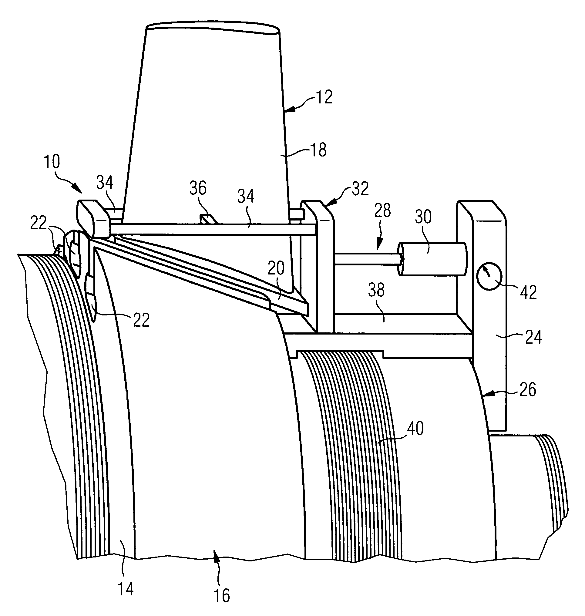
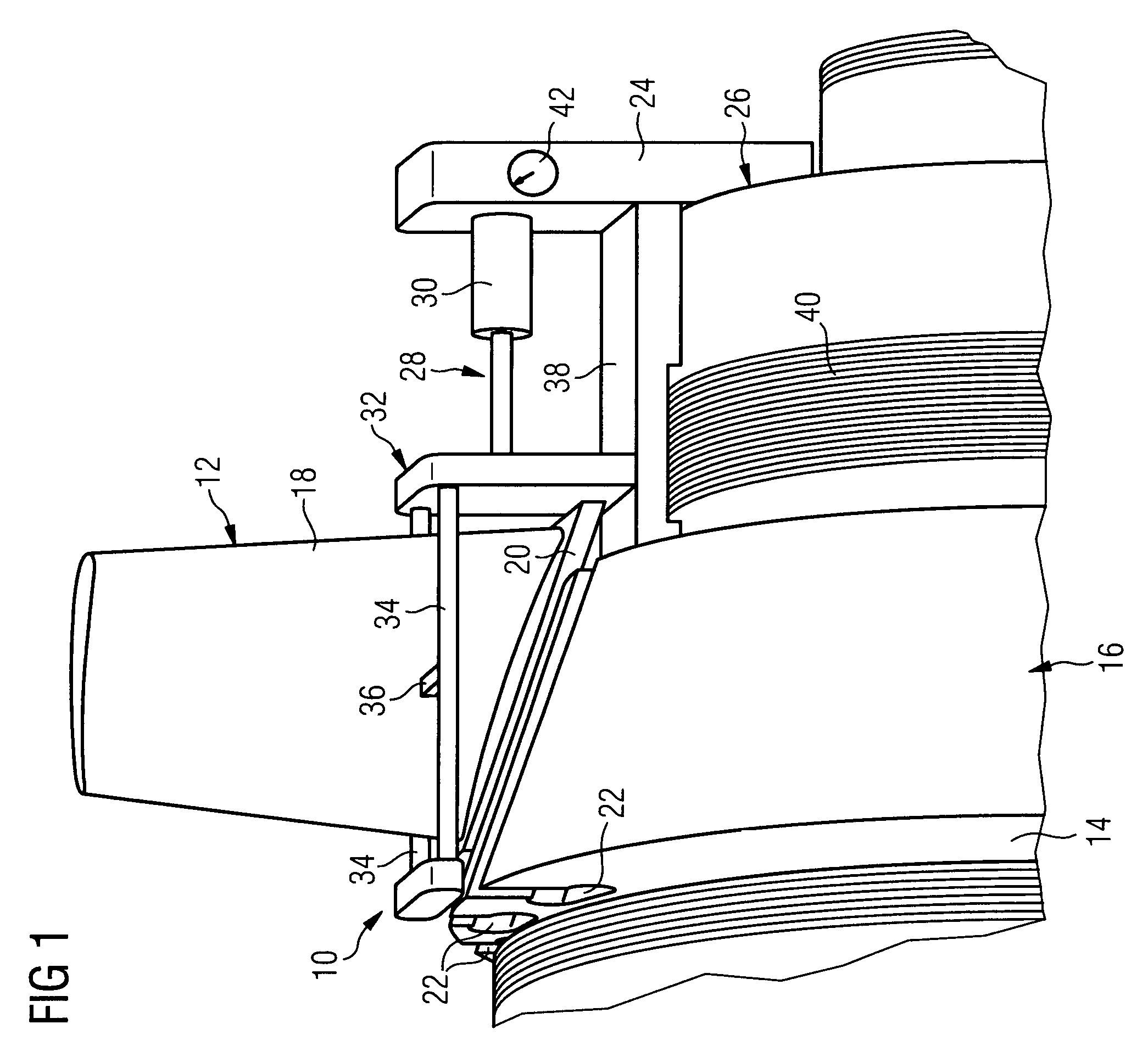
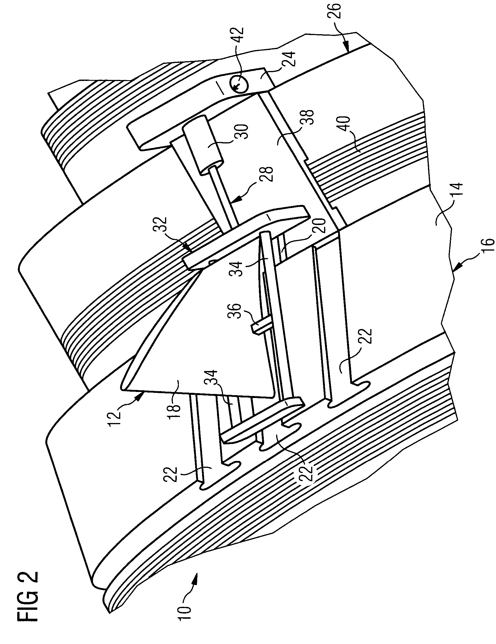
[0022]FIGS. 1 and 2 illustrate a device 10 for the demounting of blades 12 of a compressor which are attached to a wheel disk 14 of a blade wheel 16 or rotor of the compressor. The blades 12 each have a blade leaf 18 which is fastened in a groove 22 of the wheel disk 14 by means of a blade root 20. The blade root 20 is in this case pushed into the groove 22 in the axial direction of the blade wheel .16.

[0023]So that of the blades 12 can be removed cost-effectively, for example for recoating, even without a time-consuming destacking of the rotor, the device 10 is provided with a supporting means 24 which can be brought to bear against a step 26 of the blade wheel 16 and be supported there.

[0024]Coupled operatively to the supporting means 24 is an actuator means 28 which is provided for moving the blade 12 mechanically out of the wheel disk 14. The actuator means 28 comprises a cylinder / piston arrangement 30 which is arranged on the supporting means 24 and on the piston of which a ten...


PUM

PropertyMeasurementUnit
weightaaaaaaaaaa
tensionaaaaaaaaaa
forceaaaaaaaaaa

Abstract

A device (10) for the demounting of blades (12), which are pushed in with a blade root (20) on a wheel disk (14) of a blade wheel (16) of a turbine or of a compressor, is designed with a support (24) which is designed to be brought to bear against at least one component of the turbine, and is designed with an actuator (28) which is coupled to the support (24) and is designed for moving the blade root (20) mechanically out of the wheel disk (14).

Description

CROSS REFERENCE TO RELATED APPLICATIONS[0001]This application claims priority of European application No. 04016250.5 EP filed Jul. 9, 2004, which is incorporated by reference herein in their entirety.FIELD OF INVENTION[0002]The invention relates to the field of the maintenance, repair and renewal of blades of a turbine or of a compressor which are pushed in with a blade root on a wheel disk of a blade wheel of such a machine and are held there.BACKGROUND OF INVENTION[0003]Blades of the abovementioned type of modern turbines or compressors, for example compressor moving blades, are provided with coatings which have to be renewed after a certain period of operation. To renew the coating, the blades have to be demounted from the turbine or the compressor. The demounting of such compressor moving blades must take place manually on account of the many different activities to be performed and is comparatively time-consuming. During the time when a blade is being demounted, work cannot be ...

Claims


Application Information

Patent Timeline
Patent Type & Authority Patents(United States)
IPC IPC(8): F03D11/00
CPCB23P6/002B23P19/025F01D5/005F01D5/3007Y10T29/49318F05D2230/60F05D2230/70
Inventor HARTMANN, MARTINPOLANZ, WERNERRINTZEL, SABINESCHRODER, PETERSHEVCHENKO, VADIMTENRAHM, THOMAS-DIETERVONNEMANN, BERND
Owner SIEMENS AG
Why Eureka
Try Eureka