Confocal microscope and multiphoton excitation microscope

a microscope and microscope technology, applied in the direction of instruments, optical elements, discharge tubes/lamp details, etc., can solve the problems of not being able to observe a fast response of the specimen, requiring a comparatively long time for acquiring one single image, and not being able to directly use, for example, a commercially available two-dimensional ccd camera

Inactive Publication Date: 2008-11-25
OLYMPUS CORP
View PDF4 Cites 6 Cited by
  • Summary
  • Abstract
  • Description
  • Claims
  • Application Information

AI Technical Summary

Benefits of technology

[0010]The present invention provides a confocal microscope and a multiphoton excitation microscope which can acquire a high-resolution confocal image or multiphoton-excitation image and which can use a commercially available CCD camera.

Problems solved by technology

However, when the laser light is two-dimensionally scanned with the galvanometer mirror, because the driving speed of the galvanometer mirror is delayed, a comparatively long time is required for acquiring one single image, which is not compatible with observing a fast response of the specimen.
Therefore, it is necessary to perform complicated control of the light detector or the line sensor, and it is thus not possible to directly use, for example, a commercially available two-dimensional CCD camera.

Method used


Image

  • Confocal microscope and multiphoton excitation microscope
  • Confocal microscope and multiphoton excitation microscope
  • Confocal microscope and multiphoton excitation microscope

Examples


Embodiment Construction

[0043]A confocal microscope 1 according to an embodiment of the present invention will be described below with reference to the drawings.

[0044]The confocal microscope 1 according to this embodiment is a laser-scanning confocal microscope.

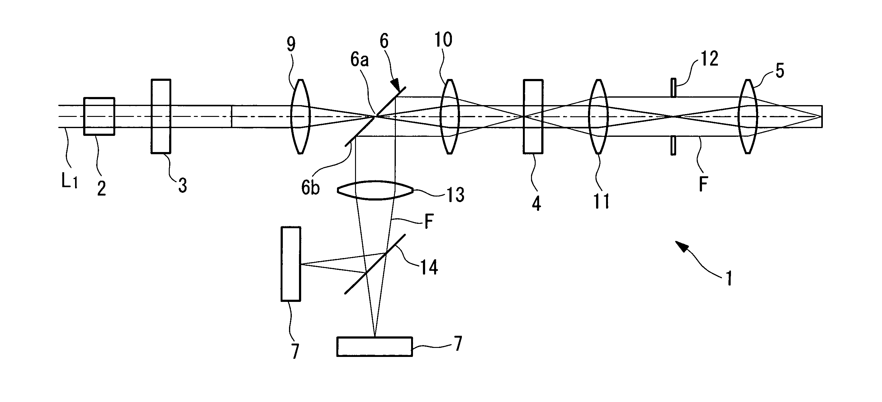
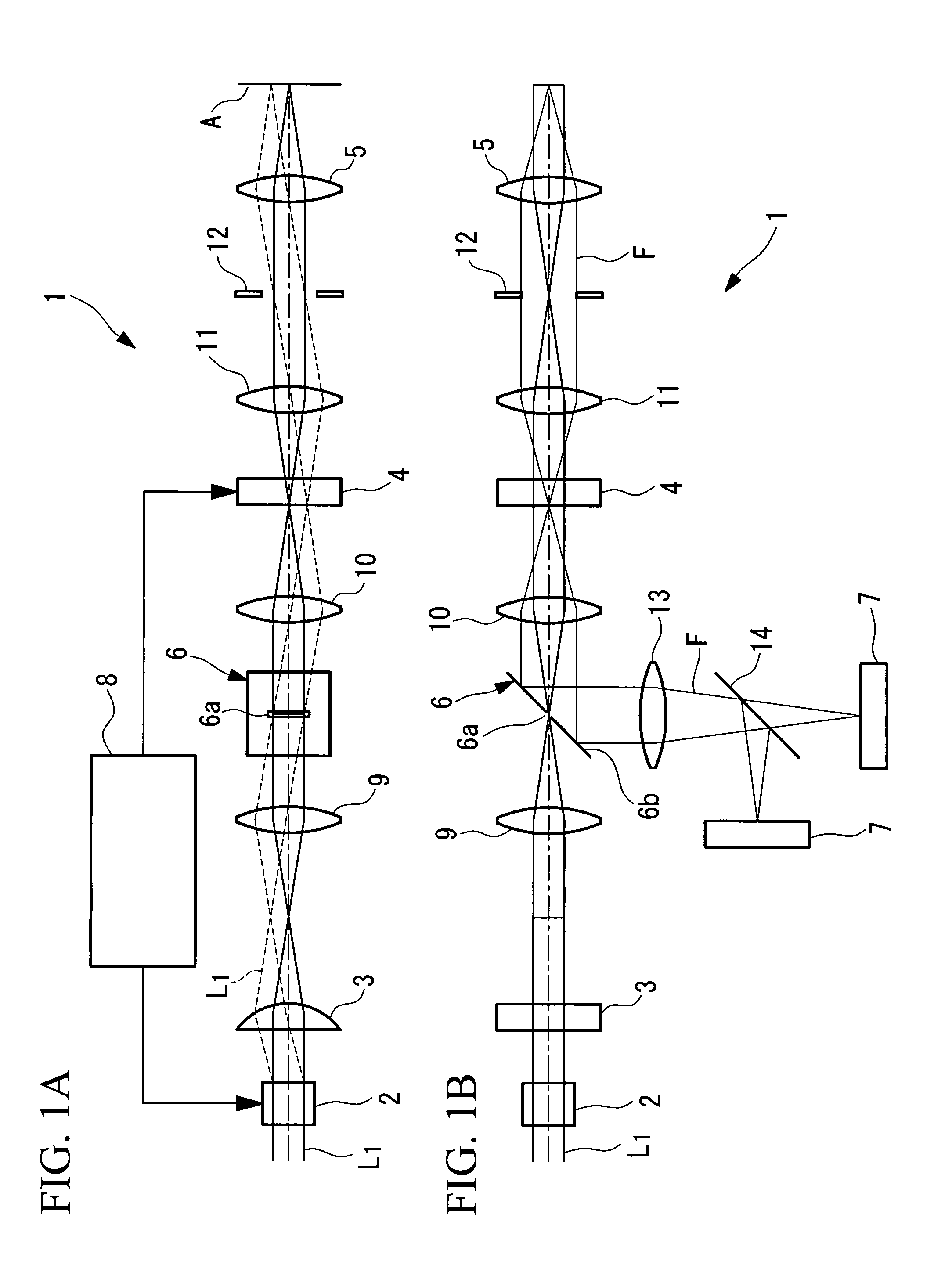
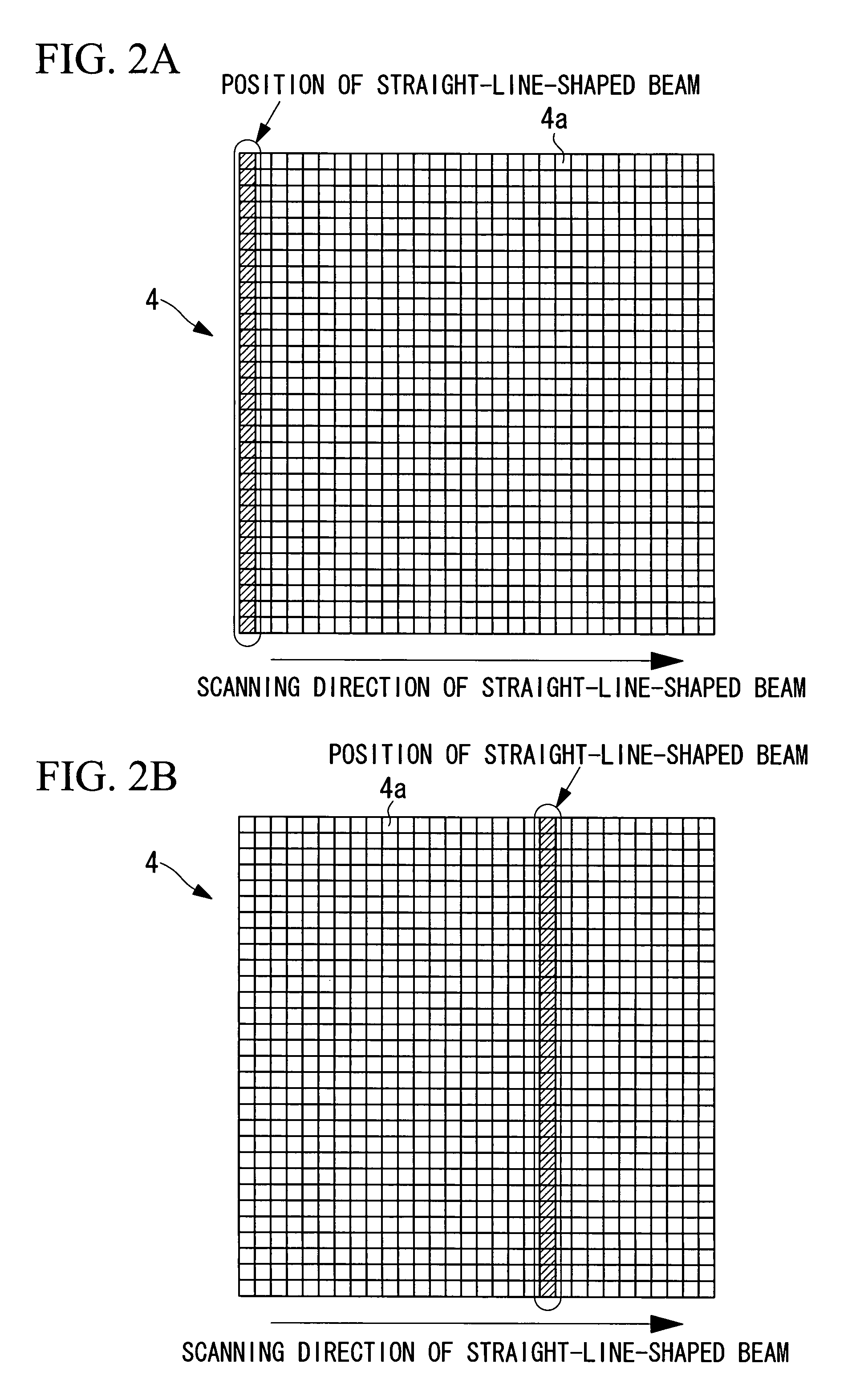
[0045]As shown in FIG. 1A and FIG. 1B, the confocal microscope 1 according to this embodiment includes a laser light source (light source; not shown in the drawing) for generating laser light L1; a light scanning unit 2 for one-dimensionally scanning the laser light L1 from the light source in one direction; a cylindrical lens (line-beam generating unit) 3 for converting the laser light L1 scanned by the light scanning unit 2 into a beam imaged in the form of a straight line; a digital mirror array device (array device) 4 in which a plurality of mirror elements (elements) 4a that can be switched on and off are two-dimensionally arrayed; an objective lens 5 for focusing the laser light L1 reflected by the mirror elements 4a in the digital mirror arra...


PUM


Abstract

The invention provides a confocal microscope comprising a light source; a light scanning unit; an array device; a line-beam generating unit for imaging illumination light in the form of a straight line extending, on the array device, in a direction intersecting the scanning direction of the light scanning unit; an objective lens for imaging the illumination light reflected or transmitted at the array device on a specimen; a beamsplitter, between the array device and the light scanning unit, for splitting off from the illumination light detection light from the specimen; a two-dimensional image-acquisition unit for acquiring the split off detection light; and a control unit for controlling the light scanning unit and the array device, wherein the array device is disposed in an optically conjugate positional relationship with a focal plane of the objective lens, and the control unit performs control so as to synchronize the light scanning unit and the array device.

Description

BACKGROUND OF THE INVENTION[0001]1. Field of the Invention[0002]The present invention relates to a confocal microscope and to a multiphoton excitation microscope.[0003]This application is based on Japanese Patent Application No. 2006-145075, the content of which is incorporated herein by reference.[0004]2. Description of Related Art[0005]A confocal microscope according to the related art is disclosed, for example, in Japanese Unexamined Patent Application, Publication No. HEI-8-271792 and US Patent Application No. 2004 / 0113059.[0006]Japanese Unexamined Patent Application, Publication No. HEI-8-271792 discloses a confocal microscope in which laser light is two-dimensionally scanned with two galvanometer mirrors, and fluorescence returning via the galvanometer mirrors is detected with a light detector such as a photomultiplier tube.[0007]US Patent Application No. 2004 / 0113059 discloses a confocal microscope in which a digital mirror array device and a one-axis galvanometer mirror are ...

Claims


Application Information

Patent Timeline
Patent Type & Authority Patents(United States)
IPC IPC(8): H01J40/14G02B21/00G02B7/04
CPCG02B21/0032G02B21/16G02B21/004
Inventor SASAKI, HIROSHIYOKOI, EIJINAKATA, TATSUO
Owner OLYMPUS CORP
Why Eureka
Try Eureka