Method and apparatus for combining laser light

Inactive Publication Date: 2008-12-02
HRL LAB
View PDF47 Cites 18 Cited by
  • Summary
  • Abstract
  • Description
  • Claims
  • Application Information

AI Technical Summary

Benefits of technology

[0018]When the multiple fibers are connected to multiple optical sources, an optical beam will emerge from the facet. The optical beam will consists of b

Problems solved by technology

Furthermore, as the optical power in each fiber is increased, this prior art has the disadvantage that the combined power must propagate in the core of the single central fiber.
When the combined optical power is high, undesirable nonlinear effects in, or damage to, the single central fiber may occur.
Further, the acoustic waves may also be amplified by this effect, generating an acoustic intensity that can easily damage the single central fiber.
Splitting a single optical source into multiple optical outputs may also be provided by the 1×N star coupler described above,

Method used


Image

  • Method and apparatus for combining laser light
  • Method and apparatus for combining laser light
  • Method and apparatus for combining laser light

Examples


Embodiment Construction

[0033]The present invention will now be described more fully hereinafter with reference to the accompanying drawings, in which preferred embodiments of the invention are shown. This invention may be embodied in many different forms and should not be construed as limited to the embodiments set forth herein. Further, the dimensions of certain elements shown in the accompanying drawings may be exaggerated to more clearly show details. The present invention should not be construed as being limited to the dimensional relations shown in the drawings, nor should the individual elements shown in the drawings be construed to be limited to the dimensions shown.

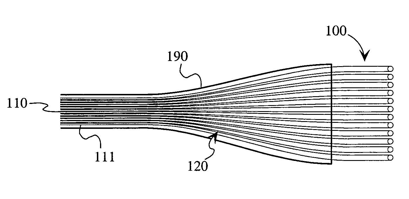
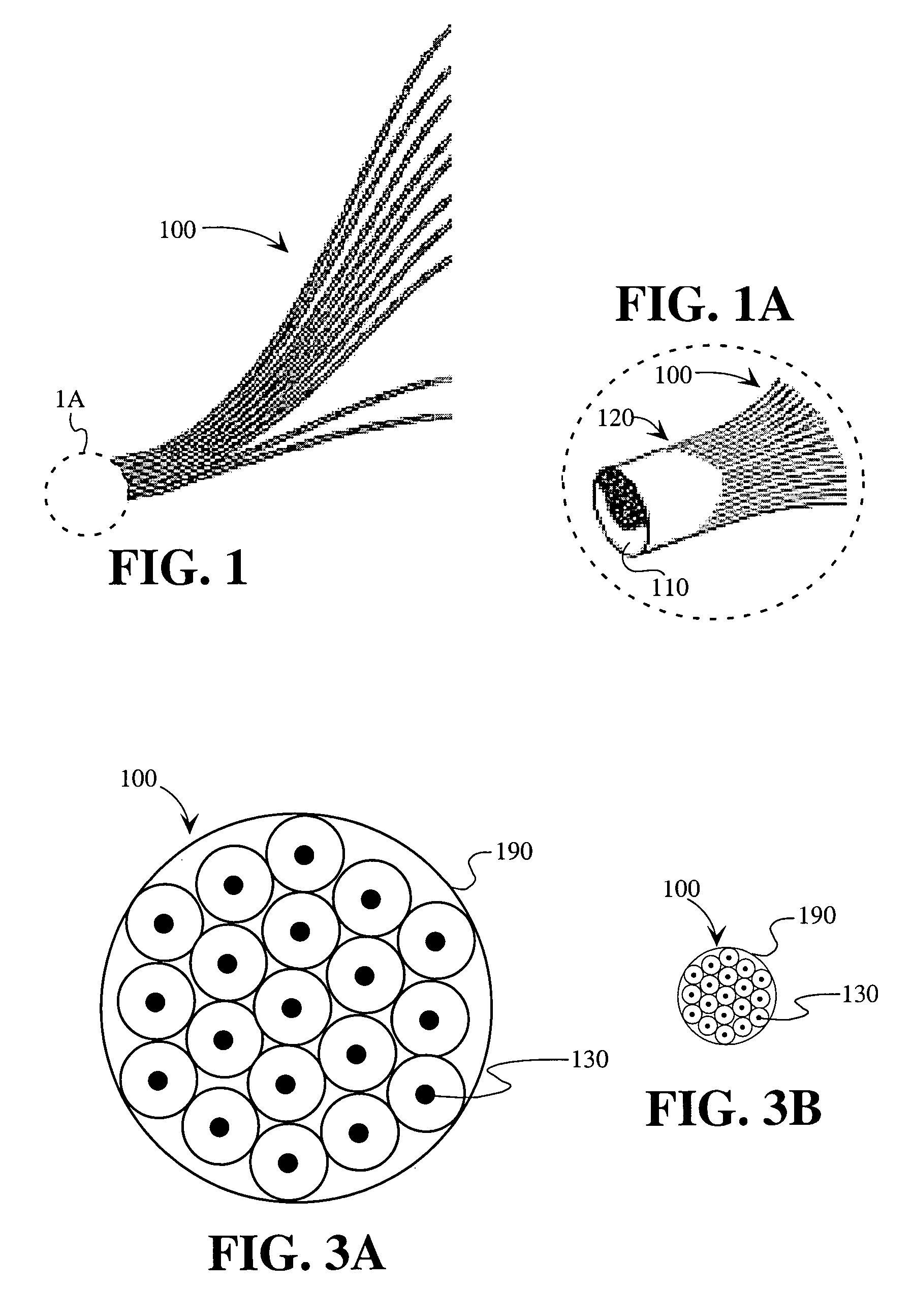
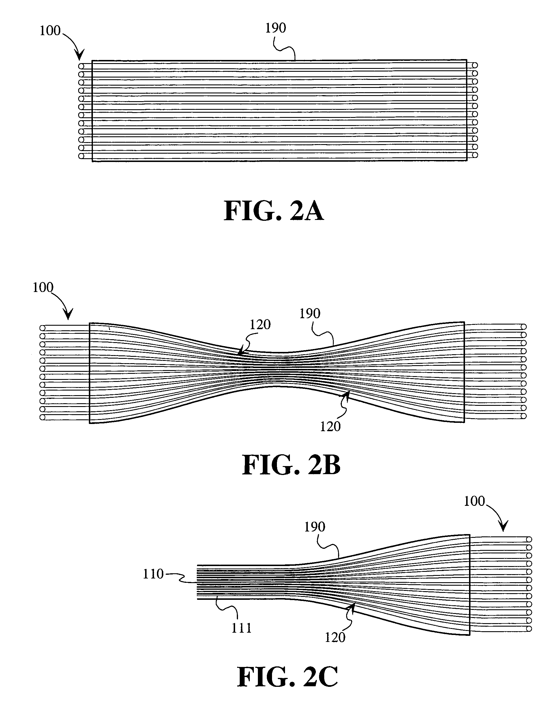
[0034]FIG. 1 illustrates the preferred embodiment of the invention, which comprises a large bundle of regularly arrayed optical fibers 100. The optical fibers 100 are preferably single-mode fibers. The optical fibers 100 are fused at one end and stretched. The fused end is cut and polished (or cleaved) to produce a facet 110 through whi...


PUM


Abstract

A fiber optic apparatus formed by fusing together multiple optical fibers and stretching the fused optical fibers to form a tapered portion. The tapered portion is cleaved or cut and polished to form a facet at which an optical beam is received or transmitted.

Description

CROSS REFERENCE TO RELATED APPLICATIONS[0001]The present application is related to and claims the benefit of co-pending U.S. Provisional Patent Application Ser. No. 60 / 441,026, filed on Jan. 17, 2003 and titled “Method and Apparatus for Combining Laser Light.” The disclosure of U.S. Provisional Patent Application No. 60 / 441,026 is incorporated herein by reference in its entirety.[0002]The subject matter of the present application may also be related to co-pending U.S. patent application Ser. No. 60 / 441,027, filed on Jan. 17, 2003 and titled “Method and Apparatus for Coherently Combining Multiple Laser Oscillators.” The disclosure of U.S. Provisional Patent Application Ser. No. 60 / 441,027 is incorporated herein by reference in its entirety.[0003]The subject matter of the present application may also be related to co-pending U.S. patent application Ser. No. 10 / 759,510 filed of even date herewith. The disclosure of this U.S. patent application Ser. No. 10 / 750,510 is incorporated herein...

Claims


Application Information

Patent Timeline
IPC IPC(8): G02B6/06G02B6/04G02B6/26G02B6/42G02B6/28G02B6/34G02B27/09G02B27/10H01S3/067H01S3/094H01S3/23
CPCG02B6/04G02B6/2808G02B27/09G02B19/0057G02B19/0028
Inventor BRUESSELBACH, HANS W.MINDEN, MONICAJONES, CRISHAMMON, DAVE
Owner HRL LAB
Why Eureka
Try Eureka