
High dynamic range time-varying integrated receiver for elimination of off-chip filters

a receiver and high dynamic range technology, applied in the field of mixers, can solve the problems of reducing the detection accuracy of low-frequency signals, and creating the need for a receiver even more sensitiv

Active Publication Date: 2008-12-02
MEDIATEK INC
View PDF15 Cites 60 Cited by
  • Summary
  • Abstract
  • Description
  • Claims
  • Application Information

AI Technical Summary

Benefits of technology

The present invention provides a quadrature mixer that overcomes known problems with traditional quadrature mixers. The mixer has a high impedance at a predetermined signal frequency and a low impedance at other frequencies. This results in improved linearity and reduced cost as there is no need for external high-Q filters. The technical effect of this invention is increased wide-band linearity in a standard radio receiver.

Problems solved by technology

Design of typical radio-frequency (RF) receivers in cellular mobile terminals are subject to several design constraints.
The first constraint is limitations on the ability to reliably detect very weak signals in the desired frequency channel.
There are several drawbacks associated with this approach however.
The first is that in-band attenuation tends to make it harder to detect weak signals, creating the need for an even more sensitive receiver after the filter.
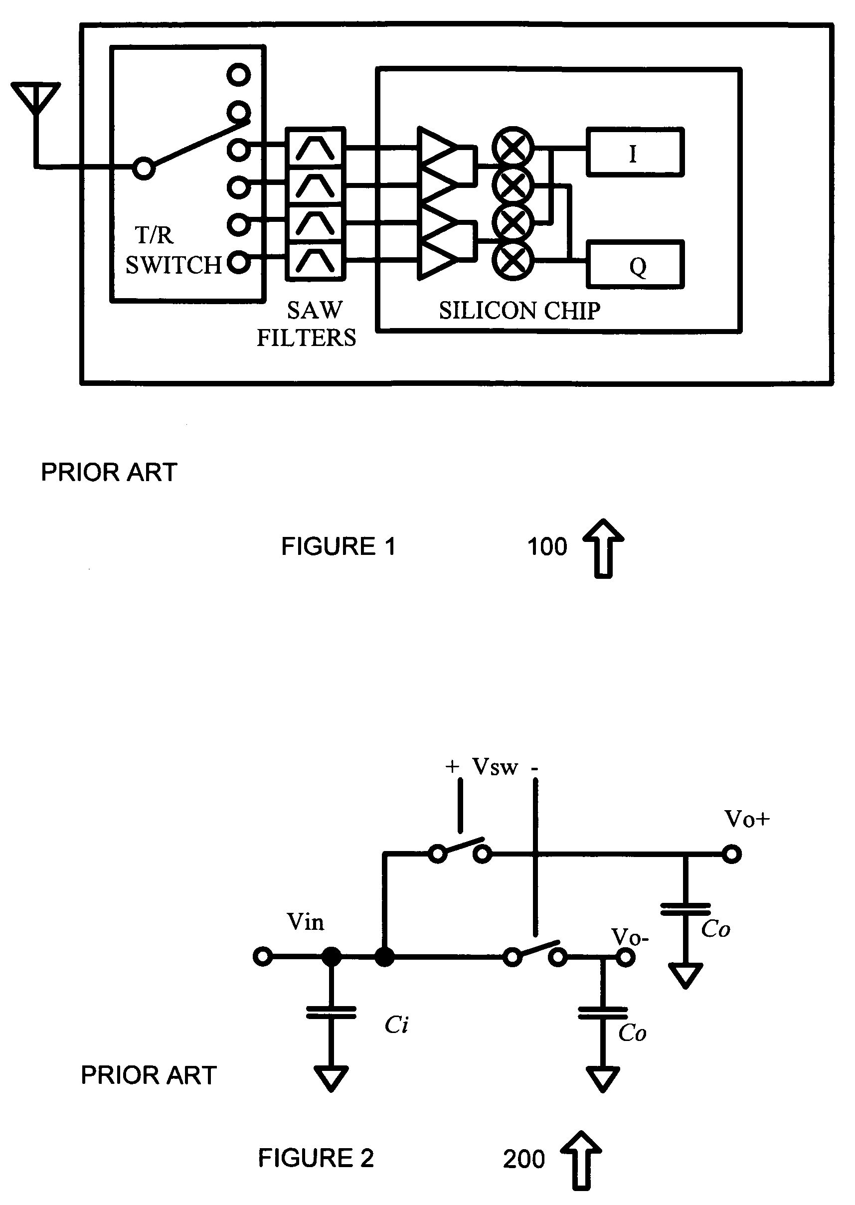
More importantly, there is currently no economical way to implement SAW filters or their equivalents in the same processes as the active circuits that follow them, which are typically produced using CMOS or BiCMOS processes and either silicon or silicon germanium technologies.
The result is that SAW filters significantly increase the cost and consume equally valuable circuit board area in a typical handset.
This problem is further exacerbated by the proliferation of different frequency bands that a mobile handset has to be compatible with.

Method used


Image

  • High dynamic range time-varying integrated receiver for elimination of off-chip filters
  • High dynamic range time-varying integrated receiver for elimination of off-chip filters
  • High dynamic range time-varying integrated receiver for elimination of off-chip filters

Examples


Embodiment Construction

[0027]In the description that follows, like parts are marked throughout the specification and drawings with the same reference numerals, respectively. The drawing figures might not be to scale, and certain components can be shown in generalized or schematic form and identified by commercial designations in the interest of clarity and conciseness.

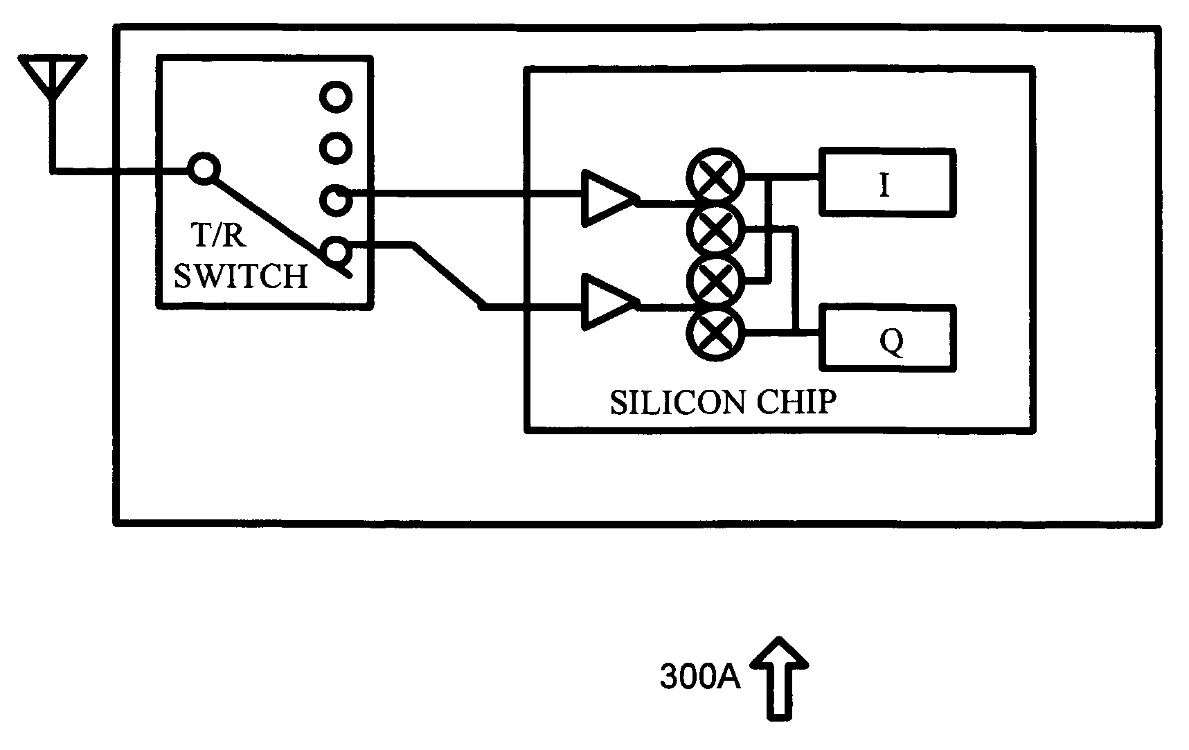
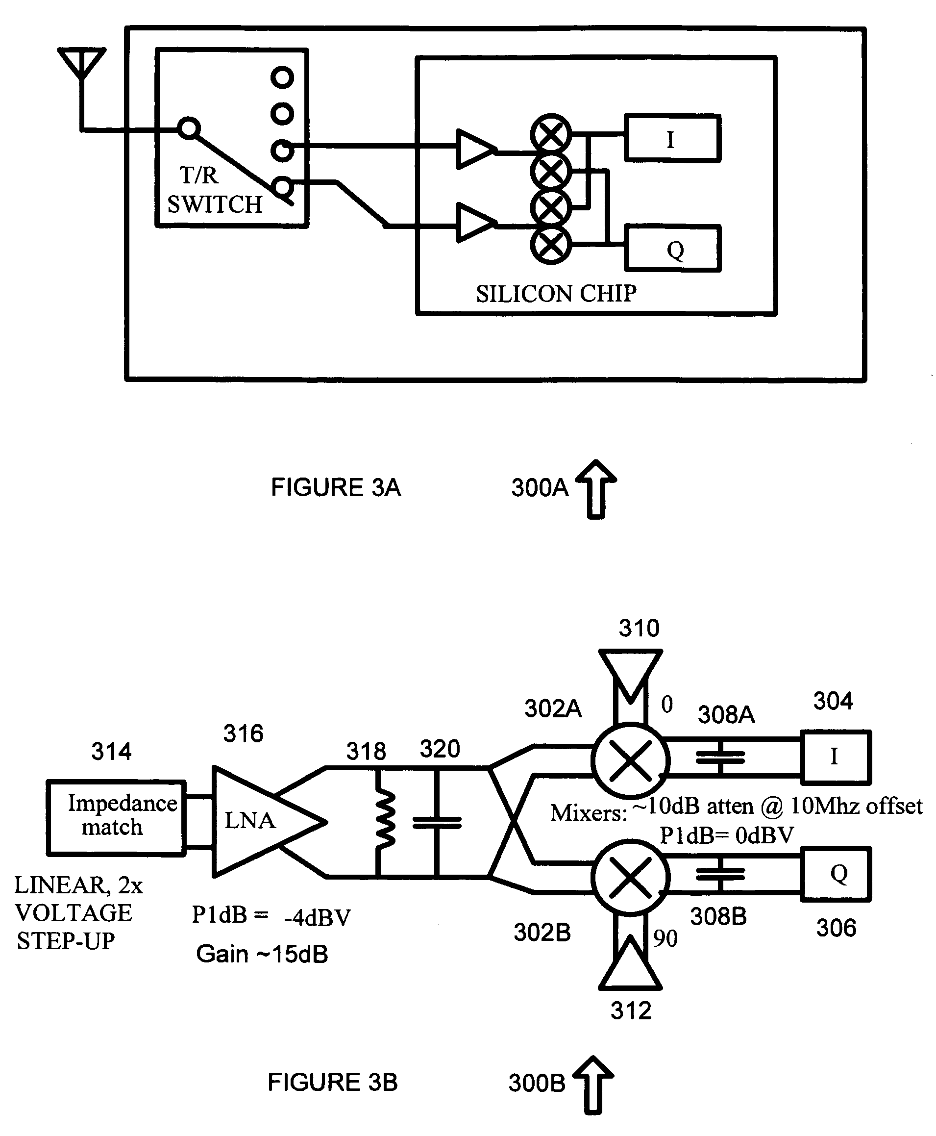
[0028]In one exemplary embodiment, the present invention permits detection of weak in-band signals in the presence of very strong out-of-band interference on a CMOS integrated circuit without the need for external high-Q filtering, such as may conventionally be achieved using SAW filters. These circuits can also be combined with a suitable LO to permit multiband operation, such as full quad-band GSM / DCS / PCS operation. In addition, the relatively wide bandwidth of the input combined with the elimination of the conventional requirement for external filters allows a reduction of the number of inputs required for the receiver in addition to a si...


PUM


Abstract

A quadrature mixer with an LO input is provided. The quadrature mixer receives a signal having a frequency FLO and a signal input having a frequency FSIG, and has an output that comprises an output impedance that is high at frequencies of |FLO−FSIG | and |FLO+FSIG| and low at other. A mixer coupled to the output impedance interacts with the output impedance such that an impedance presented at the signal input is high for signals at FSIG if FSIG is a predetermined signal frequency, and low at other frequencies.

Description

RELATED APPLICATIONS[0001]This application claims priority to U.S. Provisional application 60 / 539,702, filed Jan. 28, 2004, which is hereby incorporated by reference for all purposes.FIELD OF THE INVENTION[0002]The present invention relates to mixers, and more specifically to a quadrature mixer where the impedance presented to a signal input is high for signals at a desired signal frequency and low at undesired frequencies.BACKGROUND[0003]Design of typical radio-frequency (RF) receivers in cellular mobile terminals are subject to several design constraints. The first constraint is limitations on the ability to reliably detect very weak signals in the desired frequency channel. The second constraint is the ability to detect only slightly stronger in-band signals in the presence of very strong interfering signals. For instance, for the GSM system, the receiver must be able to reliably detect signals with a strength of −108 dBm in the absence of interference and a strength of −99 dBm w...

Claims


Application Information

Patent Timeline
Patent Type & Authority Patents(United States)
IPC IPC(8): H04B1/26H04B1/28H03D7/14H03H19/00H04B1/30H04B1/48H04M1/00
CPCH03D7/1441H03H19/004H04B1/006H04B1/48H03D7/1466H03D7/1483H03D7/165H03D7/1458H03D2200/0088H03D7/14H04B1/30
Inventor MOLNAR, ALYOSHAMAGOON, RAHUL
Owner MEDIATEK INC
Learn More