Electroluminescent device with a low refractive layer and a light scattering layer

a technology of light scattering layer and low refractive layer, which is applied in the direction of discharge tube luminescnet screen, discharge tube/lamp details, electric discharge lamps, etc., can solve the problem that the method cannot be extracted outside the device, and does not take into account the reflection of light at the boundary surface between the transparent electrode layer and the low-refractive layer

Active Publication Date: 2008-12-09
MITSUBISHI CHEM CORP
View PDF15 Cites 21 Cited by
  • Summary
  • Abstract
  • Description
  • Claims
  • Application Information

AI Technical Summary

Benefits of technology

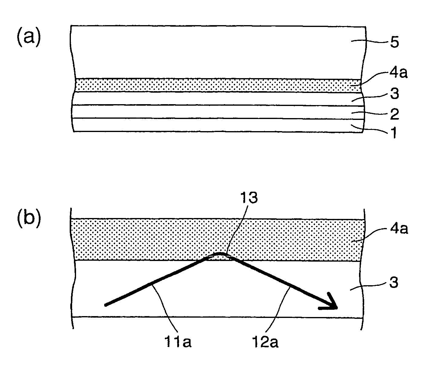
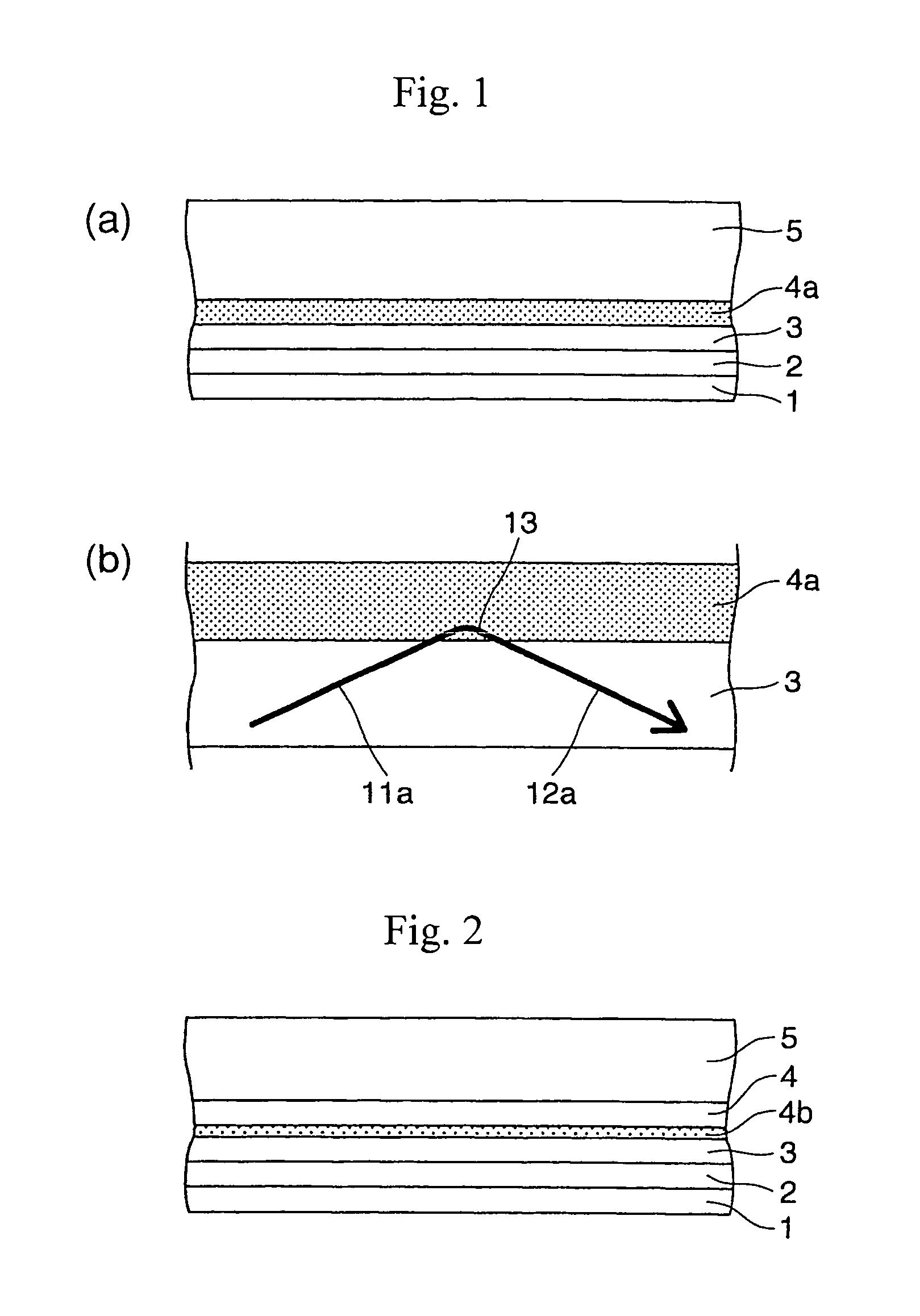
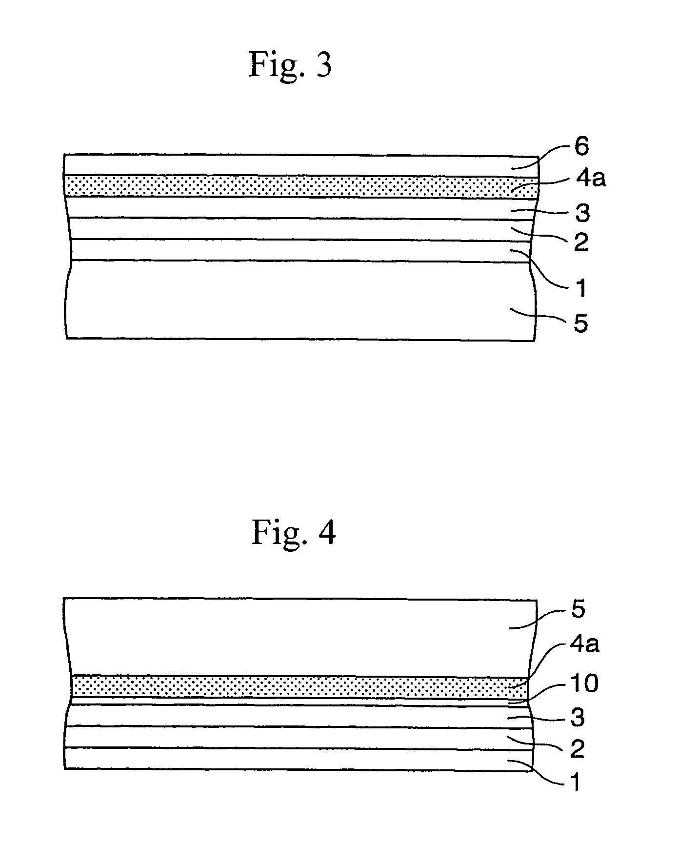
[0011](3) In a first aspect of the second invention, there is provided an electroluminescent device successively comprising a cathode, an electroluminescent layer, a transparent electrode layer and a transparent sheet / plate, wherein an evanescent light-scattering layer (A) comprising a matrix composed of a low-refractive material containing light-scattering particles is provided between the transparent electrode layer and the transparent sheet / plate, and a barrier layer is provided between the evanescent light-scattering layer (A) and the transparent electrode layer to prevent a material within the evanescent light-scattering layer (A) from being transferred into the transparent electrode layer.
[0012]The barrier layer having a refractive index substantially identical to or higher than that of the transparent electrode layer as well as a light absorption in a visible range lower than that of the transparent electrode layer, causes a part of guided light in the transparent electrode layer to be transferred thereinto, and prevents attenuation of light upon light guide. Therefore, it is also expected to attain such an effect of further improving the light extraction efficiency.
[0013](4) In a second aspect of the second invention, there is provided an electroluminescent device successively comprising a cathode, an electroluminescent layer, a transparent electrode layer, a low-refractive layer and a transparent sheet / plate, wherein an evanescent light-scattering layer (A) comprising a matrix composed of a low-refractive material containing light-scattering particles is provided between the transparent electrode layer and the low-refractive layer; a barrier layer is provided between the evanescent light-scattering layer (A) and the transparent electrode layer to prevent a material within the low-refractive layer from being transferred into the transparent electrode layer; and the matrix constituting the evanescent light-scattering layer (A) has a refractive index which is substantially identical to that of the low-refractive layer and is lower than that of the transparent electrode layer.
[0017](8) In a second aspect of the fourth invention, there is provided an electroluminescent device successively comprising a cathode, an electroluminescent layer, a transparent electrode layer, a low-refractive layer and a transparent sheet / plate, wherein a high-refractive layer having a refractive index substantially identical to that of the transparent electrode layer is provided between the transparent electrode layer and the transparent sheet / plate, and a boundary surface between the high-refractive layer and the transparent sheet / plate is provided with light-scattering roughness.

Problems solved by technology

However, this method has failed to take account of reflection of light at a boundary surface between the transparent electrode layer and the low-refractive layer.
Rather, in the method, there tends to be caused such a problem that the provision of the low-refractive layer promotes total reflection of light at the boundary between the transparent electrode layer and the low-refractive layer.
The total reflection light thus produced is attenuated upon light guide due to reflection caused inside of the transparent electrode layer and the light-emitting layer as well as at the cathode, and, therefore, cannot be extracted outside from the device.

Method used


Image

  • Electroluminescent device with a low refractive layer and a light scattering layer
  • Electroluminescent device with a low refractive layer and a light scattering layer
  • Electroluminescent device with a low refractive layer and a light scattering layer

Examples


examples

[0224]The present invention is described in more detail by Reference Examples corresponding to Examples, but the Reference Examples are only illustrative and not intended to limit the scope of the present invention. Meanwhile, in the following Reference Examples and Comparative Examples, neither cathode nor electroluminescent layer were formed, and a fluorescent pigment layer was formed on a transparent electrode layer. The fluorescent pigment layer was irradiated with excitation light to extract a fluorescence from the side of a substrate and measure an amount of light extracted using a fluorescence spectrometer / luminance meter manufactured by Hitachi Ltd., in the following procedure. That is, excitation light having a wavelength of not more than 400 nm was irradiated on a rear surface (the side on which fluorescent pigment was vapor-deposited) of the obtained laminate, from the side of the fluorescent pigment layer, and an intensity of the extracted light having a wavelength of 42...

reference examples 1 to 5

[0227]These Reference Examples were conducted for explaining the first invention.

reference example 1

Corresponding to Embodiment (1)

[0228]A glass plate having a thickness of 0.7 mm and a size of 75 mm square which was composed of a non-alkali glass “AN100” produced by Asahi Glass Co., Ltd., was immersed in 0.1N nitric acid for about one hour to subject the surface thereof to degreasing treatment, washed with pure water and then dried in an oven at 60° C., thereby obtaining a glass substrate 1.

[0229]Separately, a small amount of an acid catalyst (aluminum acetylacetonate) was added to a mixed solution containing 30% by weight of an oligomer of tetramethoxysilane (“MS51” produced by Mitsubishi Chemical Corporation), 50% by weight of BtOH, 8% by weight of desalted water and 12% by weight of MeOH, and then silica fine particles having an average particle size of 120 nm and containing particles having a particle size of from 70 to 150 nm in an amount of not less than 60% by weight, were added to the resultant solution such that the weight ratio of the silica fine particles to MS51 was 1...


PUM


Abstract

The electroluminescent device successively comprises a cathode, an electroluminescent layer, a transparent electrode layer, an evanescent light-scattering layer comprising a matrix composed of a low-refractive material containing light-scattering particles, and a transparent sheet / plate. Such an electroluminescent device is decreased in total reflection not only at a boundary surface between a transparent substrate and an outside air layer but also at a boundary surface of the transparent electrode layer on its light extraction side, and therefore, is considerably improved in light extraction efficiency. In addition, in the electroluminescent device provided with a barrier layer, the transparent electrode layer and the electroluminescent layer can be well protected so that deterioration of electroluminescent pigments and occurrence of dark spots can be effectively prevented, resulting in enhanced life of the device.

Description

[0001]This application is a continuation of PCT / JP2004 / 003159, filed 11 Mar. 2004, claiming priority of JP 2003-066845, filed 12 Mar. 2003; JP 2003-066846, filed 12 Mar. 2003; JP 2003-073943, filed 18 Mar. 2003; and JP 2003-113055, filed 17 Apr. 2003. The entire contents of each of which are incorporated herein by reference.TECHNICAL FIELD[0002]The present invention relates to electroluminescent (EL) devices, and more particularly to electroluminescent devices capable of extracting light from an electroluminescent layer thereof at a high efficiency.BACKGROUND ART[0003]Conventional electroluminescent devices used in EL displays or EL illumination apparatuses have a layer structure including a cathode, an electroluminescent layer, a transparent electrode (anode) and a transparent substrate. These electroluminescent devices are operated by utilizing such a light emission principle that holes injected from the anode and electrons injected from the cathode are recombined with each other ...

Claims


Application Information

Patent Timeline
Patent Type & Authority Patents(United States)
IPC IPC(8): H01J63/04H01L51/52H05B33/02H05B33/14H05B33/22
CPCH01L51/5268H01L51/5237H10K59/873H10K59/877H10K59/871H05B33/22H05B33/14H05B33/02H10K50/854H10K50/841H10K50/844
Inventor HANDA, KEISHINARAMAKI, SHINJIAYA, TETSUYA
Owner MITSUBISHI CHEM CORP
Why Eureka
Try Eureka