RFID tag

a radio frequency identification and tag technology, applied in the field of rfid (radio frequency identification) tags, can solve the problems of deteriorating reliability, radio communication with the antenna pattern being obstructed by the metal case, and the temperature inside the metal case may exceed the temperature guaranteed for the circuit chip if left in a high temperature for a long tim

Inactive Publication Date: 2008-12-09
FUJITSU LTD
View PDF6 Cites 16 Cited by
  • Summary
  • Abstract
  • Description
  • Claims
  • Application Information

AI Technical Summary

Benefits of technology

[0010]According to the invention, the inlet having the circuit chip which is not resistant to a high temperature environment is double protected by the thermal storage section and the thermal insulating section. Environmental temperature, at first, is insulated by the thermal insulating section which has a relatively low thermal conductivity and relatively high thermal insulation. For this reason, heat conducted to the thermal storage section which encloses the inlet is suppressed. In addition, because the thermal storage section has a relatively low thermal diffusivity and relatively high thermal storage, heat is transmitted to the inlet so slowly that a temperature increase of the inlet itself can be suppressed for a long time. In other words, the RFID tag according to an aspect of the invention is capable of tolerating a high temperature environment. Further, in the RFID according to the invention, since both the thermal insulating section and the thermal storage section are made of a nonmetal, radio waves are not disturbed, resulting in good performance of radio communication by the inlet.
[0012]According to the preferable form above, it is also possible to protect the inlet mechanically.

Problems solved by technology

The temperature resistance of a circuit chip mounted in such a RFID tag is guaranteed at best for a ten-year usage under an environment of 55° C. Under an environment of over such guaranteed temperature, there arises a problem that the reliability is deteriorated.
In the vacuum insulation described above, however, an antenna pattern connected to a circuit chip is encased together with the circuit chip in a metal case, thereby causing radio communication with the antenna pattern to be obstructed by the metal case.
In addition, because a polystyrene foam, a general thermal insulating material, has a low thermal capacity, the temperature inside the metal case may exceed the temperature guaranteed for a circuit chip when left in a high temperature for a long time.

Method used


Image

  • RFID tag
  • RFID tag
  • RFID tag

Examples


Embodiment Construction

[0018]An exemplary embodiment will be described with reference to the drawings.

[0019]FIG. 1 is a diagram showing an embodiment of a RFID tag according to the invention.

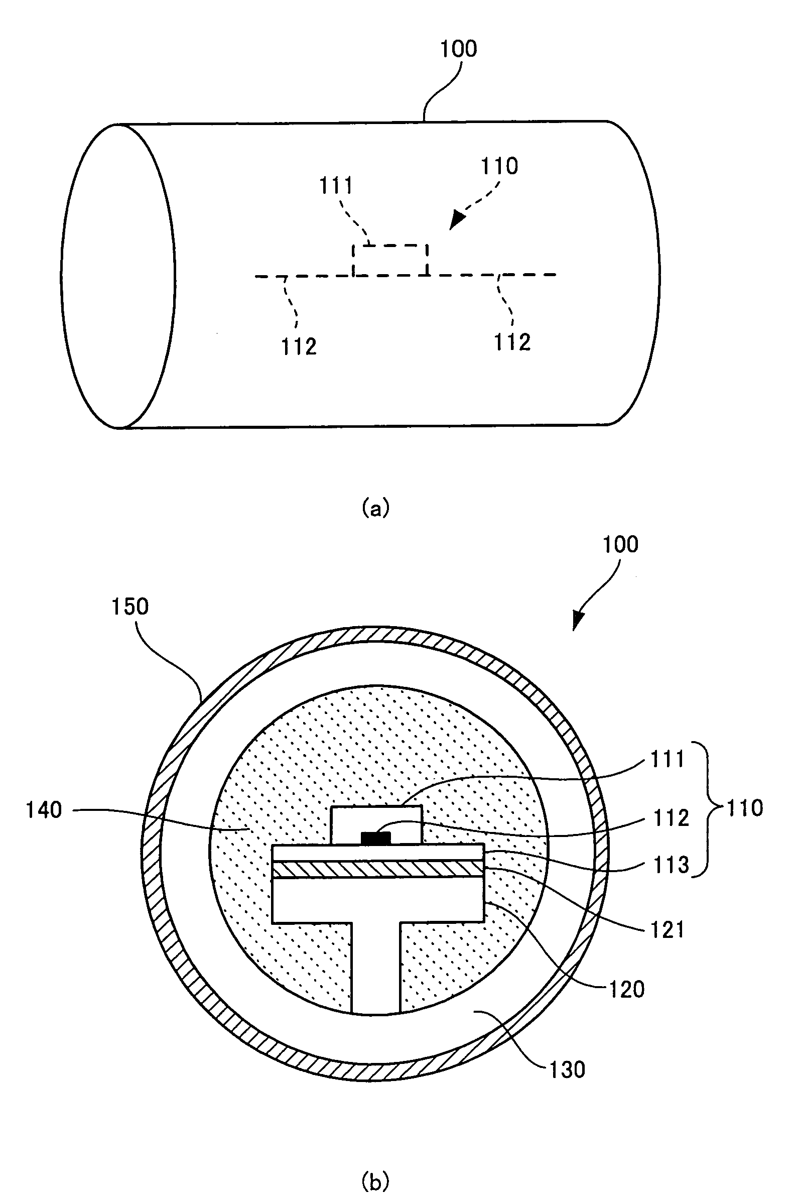
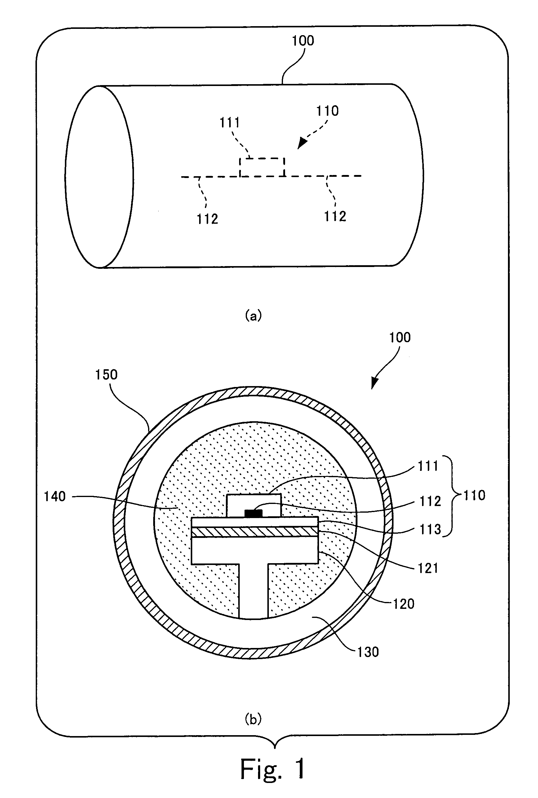
[0020]In Part (a) of FIG. 1 is shown an external view of a RFID 100 according to an embodiment of the invention. In Part (b) of FIG. 1 is shown a sectioned view of the RFID tag 100 when it is cut in a plane perpendicular to the center axis thereof.

[0021]The RFID tag 100 shown in FIG. 1 includes an inlet 110 in which an antenna pattern 112 forming an antenna for radio communication and formed on a base 113 is electrically connected to a circuit chip 111 which performs radio communication with the antenna, a supporting platform 120 made of temperature-resistant plastic to which the inlet 110 is fixed with an adhesive agent 121, a case 130 with a cylindrical shape and made of temperature-resistant plastic on part of which the supporting platform 120 is fixed, a thermal storage section 140 enclosed with a thermal storage ...


PUM


Abstract

A RFID tag includes an inlet in which an antenna for communication and a circuit chip performing radio communication with the antenna are electrically connected to each other. The RFID tag further includes a thermal storage section which encloses the inlet, which is made of a nonmetal, and which prevents thermal diffusion into the inlet and a thermal insulating section which encloses the thermal storage section, which prevents thermal conduction to the thermal storage section, and which has higher thermal diffusivity than thermal diffusivity of the thermal storage section and lower thermal conductivity than thermal conductivity of the thermal storage section.

Description

BACKGROUND OF THE INVENTION[0001]1. Field of the Invention[0002]The present invention relates to a RFID (Radio_Frequency_Identification) tag which exchanges information with an external device without contacting the device. Among persons skilled in the art of the field of the invention, the RFID tag used in the invention may also be called a “Wireless IC tag”.[0003]2. Description of the Related Art[0004]Recent years there have been proposed various RFID tags which exchange information with an external device typified by a reader and writer using a radio wave without contacting the device (for example, see Japanese Patent Laid-Open Nos. 2000-311226, 2000-200332 and 2001-351082). One such RFID tag is provided with an antenna pattern for radio communication and a circuit chip both mounted on a base sheet made of a plastic or paper. Applications for such a RFID tag include discriminations of an article attached to the RFID tag through exchange of information of the article with an outsi...

Claims


Application Information

Patent Timeline
Patent Type & Authority Patents(United States)
IPC IPC(8): G08B13/14
CPCG06K19/077G06K19/0773G06K19/07
Inventor BABA, SHUNJIJIE, WEI
Owner FUJITSU LTD
Why Eureka
Try Eureka