Directional antenna configuration for TDD repeater

a repeater and directional antenna technology, applied in the direction of resonant antennas, wireless communication, radiating element structural forms, etc., can solve the problems of difficult to achieve high isolation between antennae, rise to interference problems, additional problems arise, etc., to achieve optimum signal performance, large influence on determining, and analysis of repeater performan

Inactive Publication Date: 2008-12-09
QUALCOMM INC
View PDF11 Cites 29 Cited by
  • Summary
  • Abstract
  • Description
  • Claims
  • Application Information

AI Technical Summary

Benefits of technology

[0008]The present invention overcomes the above problems by providing an exemplary antenna array configuration in which two closely spaced patch antennae are combined with a dipole antenna such that one of the patch antennae can be selected depending on the orientation of the repeater package to communicate with a base station, AP, or the like, and the dipole antenna can be directed generally toward a client device such as a subscriber device, a user device, a wireless communication node, or the like. The patch antennae and the dipole antenna are orthogonally polarized to increase isolation and reduce electromagnetic coupling between the patch and dipole antennae. The antennae can be fed in a balanced configuration to reduce common mode currents. The use of multiple switched directional antennae allows for minimal user interaction during initial configuration and the repeater electronics may be utilized for automatic selection of the best directional antenna for use during initial configuration, and also periodically during operation.
[0010]It will be appreciated that placement of the repeater unit will have a large impact on determining the signal quality both toward the base station and between the repeater client or clients. Therefore, repeater performance can be analyzed and a user could be directed to reposition the repeater unit for optimum signal performance. In accordance with the present invention, the use of two or more switchable patch antennae can address the placement issue to an extent by allowing the system to select which of the patch antenna will provide the best reception toward the base station.

Problems solved by technology

Further, enclosing antenna modules and repeater circuitry within the same package is desirable for convenience, manufacturing cost reduction and the like, but such packaging can give rise to interference problems.
Difficulties arise however, in that the use of antennae with high directivity requires that directional alignment with the base station or AP be performed, typically by trial-and-error manual alignment.
Additional problems arise however when packaging repeater antennae and circuitry in close proximity.
First, it becomes difficult to achieve high isolation between antennae due solely to the close physical proximity even where directional antennae are used.
Isolation becomes even more difficult where antennas having omni directional antenna patterns are used and where the proximity of the repeater to structures such as walls, furniture or other objects cannot be anticipated, and thus cannot be compensated for in advance due to unknown such as the final placement of the repeater module.
Simply put, as the antennae are placed closer together, the more likely the antennae will couple energy into each other, which reduces the isolation between the sides of the repeater.
Maintaining an omni or semi-omni directional antenna pattern becomes difficult since overlapping radiation patterns of antennae which are placed close to each other tend to generate interference effects.
While the use of direction antenna can benefit the repeater in terms of increased range and reduced wireless signal variation due to Raleigh fading effects, directional antennas are not typically used for indoor applications, due to the requirement for directional alignment, which is beyond the capability or desire of the average user.
Such cancellation however can be expensive in that additional circuitry is required, and can be computationally expensive in that such cancellation can result in the introduction of a delay factor in the repeater or alternatively can require the use of more expensive and faster processors to perform the cancellation function.

Method used


Image

  • Directional antenna configuration for TDD repeater
  • Directional antenna configuration for TDD repeater
  • Directional antenna configuration for TDD repeater

Examples


Embodiment Construction

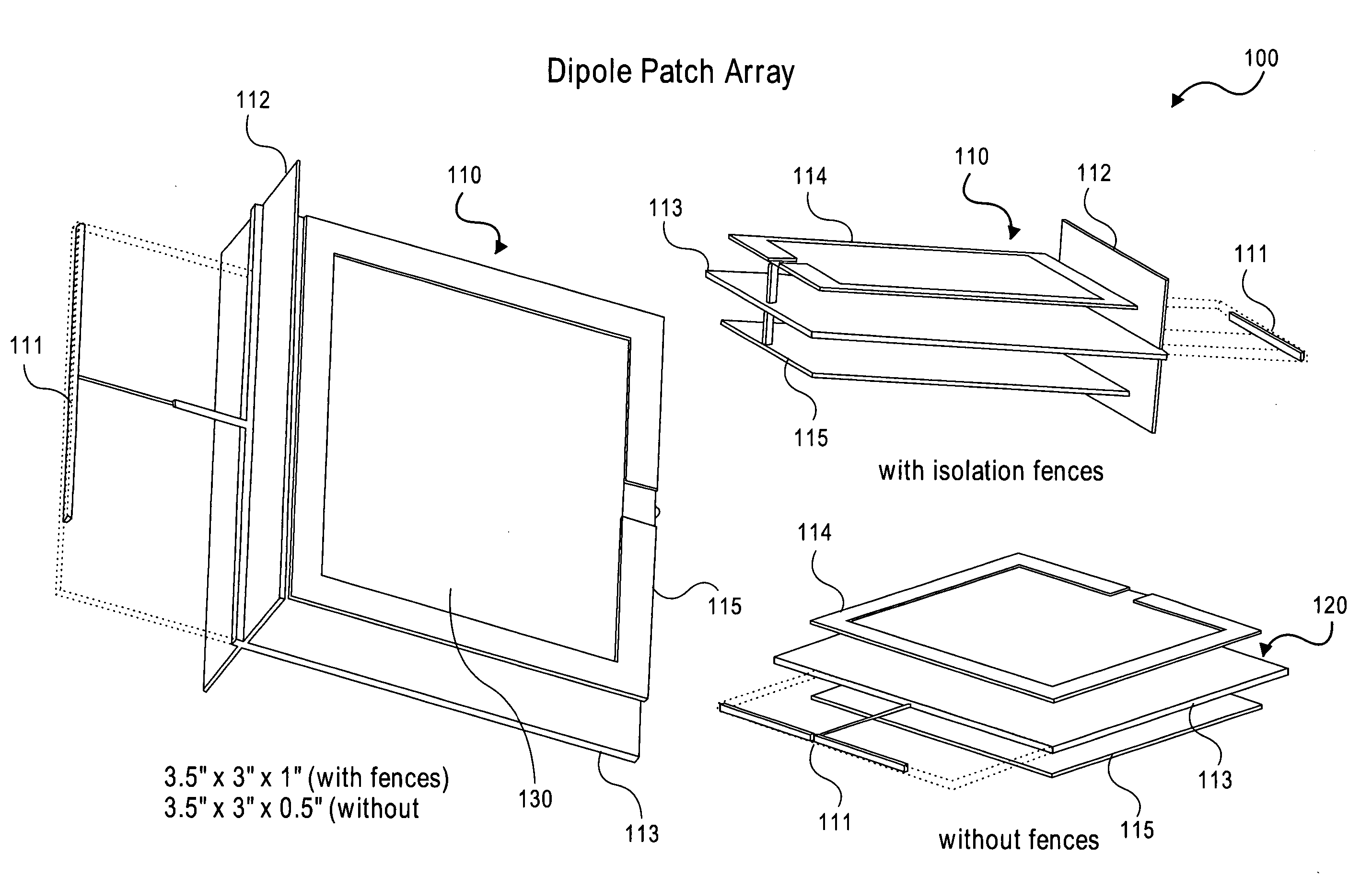
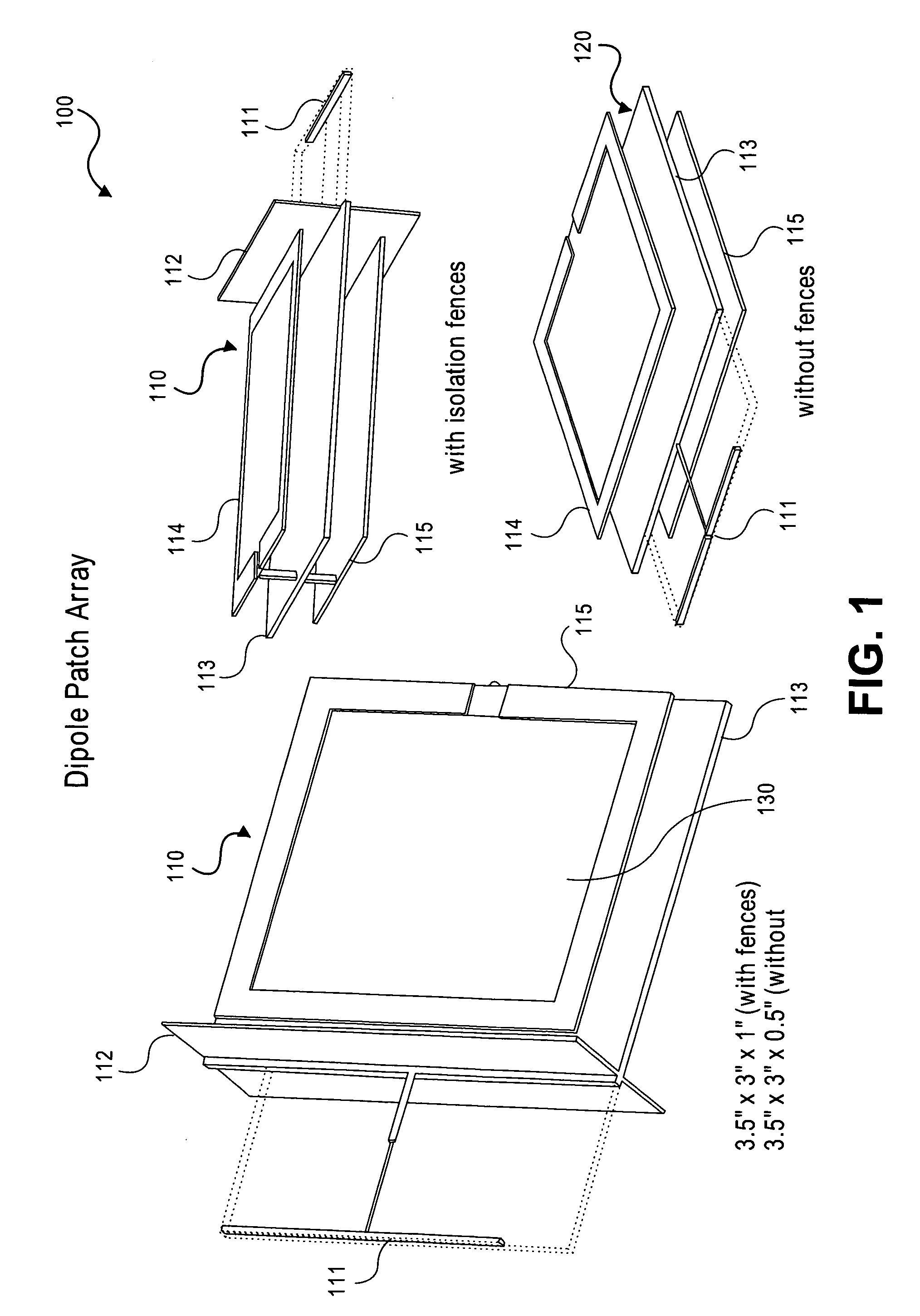
[0029]A directional antenna configuration is disclosed and described herein for a wireless communication node such as a TDD repeater. The exemplary antenna configuration can include a monopole, a dipole, or an alternative omni-directional or quasi omni-directional antenna element or configuration such as an “F” shaped antenna or the like, facing a client side of the repeater and two patch antennae facing the base station side of the repeater. The patch antennae are arranged in parallel relation to each other and in relation to a ground plane arranged therebetween and extending beyond the patch antennae on one side, such as the client side. The client side element can be arranged on the ground plane and, as noted, can be a monopole antenna, a dipole antenna, or the like. The patch antennae are both orthogonally polarized with respect to the client side antenna and are preferably vertically polarized, while the client side antenna is horizontally polarized. Either one of the two patch...


PUM


Abstract

A wireless communication node, such as a repeater, including a frequency translating repeater, a physical layer (PHY) repeater, time divisional duplex repeater (TDD) and the like, is configured with a pair of directional patch antennae and an omni-directional antenna. The patch antennae can be selected depending on the orientation of the repeater package to communicate with a station such as an access point or a base station. The omni-directional antenna can be directed toward another station such as a client. The patch antennae and the omni-directional antenna can be orthogonally polarized to increase isolation and reduce electromagnetic coupling. Multiple antennae can be used in multiple-input-multiple-output (MIMO) configurations.

Description

CROSS REFERENCE TO RELATED APPLICATIONS[0001]The present invention is related to and claims priority from U.S. Provisional Patent Application No. 60 / 738,579, filed Nov. 22, 2005 entitled “DIRECTIONAL ANTENNA CONFIGURATION FOR TDD REPEATER,” the contents of which are incorporated herein by reference.FIELD OF THE INVENTION[0002]The present invention relates generally to wireless communication and more specifically to an antenna configuration associated with a wireless Time Division Duplex (TDD) repeater, the antenna configuration made up of closely packaged antennas having orthogonal polarization and isolation to reduce electromagnetic coupling and to provide high directivity.BACKGROUND OF THE INVENTION[0003]In a wireless communication node, such as a TDD repeater designed to operate with a TDD based wireless system capable of simultaneous transmission and reception of TDD packets, the orientation of the antenna units is crucial in establishing non-interfering operation as it is criti...

Claims


Application Information

Patent Timeline
Patent Type & Authority Patents(United States)
IPC IPC(8): H01Q1/38
CPCH01Q1/38H01Q7/00H01Q19/10H04B7/1555H04W88/085H04B7/14H04W88/08
Inventor GAINEY, KENNETH M.PROCTOR, JR., JAMES A.SNYDER, CHRISTOPHER A.OTTO, JAMES C.
Owner QUALCOMM INC
Why Eureka
Try Eureka