Precision thrust/sun tracking attitude control system for gimbaled thruster

a technology of gimbal thruster and attitude control system, which is applied in vehicle position/course/altitude control, process and machine control, instruments, etc., can solve the problems of large solar array or large batteries with commensurate mass and cost penalties

Inactive Publication Date: 2008-12-16
LOCKHEED MARTIN CORP
View PDF5 Cites 24 Cited by
  • Summary
  • Abstract
  • Description
  • Claims
  • Application Information

AI Technical Summary

Benefits of technology

[0007]In one exemplary embodiment, a control arrangement is provided that alternately employs two sun / thrust tracking strategies or modes on an automatic basis. The two strategies involve ideal thrust / sun tracking and predictive thrust / sun tracking respectively. The predictive mode is used to mitigate or avoid the singularity condition that can occur for small angular separation between the thrust trajectory and sun vectors.
[0009]The present invention may provide a number of advantages and / or benefits. For example, the present invention improves sun-pointing performance by taking control action based on the predicted movement of the thrust trajectory vector relative to the sun vector in the proximity region where the angular separation of the thrust and sun vectors is small. Based on the disclosure and teachings provided herein, a person of ordinary skill in the art will realize other advantages and benefits provided by the present invention.

Problems solved by technology

While constraining the rotation rate may be effective, it can also create large solar array sun pointing errors which, in turn, may result in the need for a larger solar array or larger batteries with commensurate mass and cost penalties.

Method used


Image

  • Precision thrust/sun tracking attitude control system for gimbaled thruster
  • Precision thrust/sun tracking attitude control system for gimbaled thruster
  • Precision thrust/sun tracking attitude control system for gimbaled thruster

Examples


Embodiment Construction

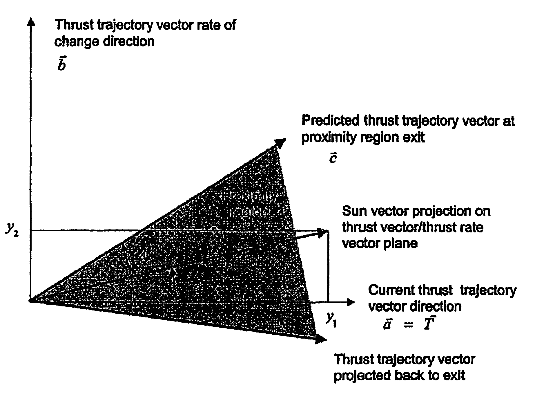
[0018]The present invention in the form of one or more exemplary embodiments will now be described. The present invention provides methods and systems that improve sun pointing, limit angular rates to specified values, and operate automatically without the need for ground support. In one embodiment, a system installed on a spacecraft alternates between two control strategies or modes, namely, an ideal thrust / sun tracking strategy outside of a proximity region and a predictive thrust / sun tracking strategy within the proximity region.

[0019]The predictive strategy is automatically invoked when the angle between a thrust trajectory vector and a sun vector is below a specified value, e.g., about 20 to 30 degrees. Based on the disclosure and teachings provided herein, a person of ordinary skill in the art will appreciate how to select the specified value. At each time step, the system predicts the thrust trajectory vector's orientation at the proximity region exit and the time until the t...


PUM


Abstract

A system for providing precision thrust and sun tracking attitude control is provided. The system determines a proximity region and alternately engages either an ideal operational mode or a predictive operational mode based on whether a thrust trajectory vector is in the proximity region in order to provide attitude control. The proximity region is determined based on an angle between the thrust trajectory vector and a sun vector. For example, the angle is about 20-30 degrees. The system engages the predictive operational mode when the thrust trajectory vector enters the proximity region. When in the predictive operational mode, the system periodically re-calculates the thrust trajectory vector and determines where the thrust trajectory vector will exit the proximity region. Based on the determination with respect to where the thrust trajectory vector will exit the proximity region, the system provides appropriate attitude control adjustment with respect to gimbaled thrusters and solar arrays so as to reduce sun-pointing errors and keep the sun in a predetermined yaw / roll plane. The system can be used in a spacecraft including a satellite.

Description

CROSS-REFERENCES TO RELATED APPLICATION(S)[0001]The present application claims the benefit of priority under 35 U.S.C. §119 from U.S. Provisional Patent Application Ser. No. 60 / 511,583, entitled “PRECISION THRUST / SUN TRACKING ATTITUDE CONTROL SYSTEM FOR HALL CURRENT THRUSTER (HCT)”, filed on Oct. 14, 2003, the disclosure of which is hereby incorporated by reference in its entirety for all purposes.BACKGROUND OF THE INVENTION[0002]The present invention generally relates to gimbaled thrusters and more particularly to a method and system for providing high-accuracy thrust trajectory tracking and solar array sun pointing during orbit transfer.[0003]Gimbaled thrusters (including Hall Current Thrusters (HCTs)) are used by spacecraft, such as military communications spacecraft, to perform partial orbit transfer. The HCTs, which are much more fuel-efficient than chemical thrusters, enable as much as 500 kg of additional payload to be delivered to the mission orbit.[0004]When used for orbit ...

Claims


Application Information

Patent Timeline
Patent Type & Authority Patents(United States)
IPC IPC(8): B64G1/24
CPCB64G1/26B64G1/363B64G1/365G05D1/0883B64G1/222B64G1/283B64G1/244
Inventor GOODZEIT, NEIL E.PATEL, MOONISH R.RATAN, SANTOSH
Owner LOCKHEED MARTIN CORP
Why Eureka
Try Eureka