
Molding material for fuel cell separator and method for preparing the same

a fuel cell separator and molding material technology, applied in the direction of cell components, final product manufacturing, sustainable manufacturing/processing, etc., can solve the problems of shortening the service life of the fuel cell, affecting the performance of the separator, and incurring much higher processing costs than before. , to achieve the effect of reducing the gas permeability, and reducing the cost of processing

Active Publication Date: 2008-12-16
HANKOOK TIRE WORLDWIDE
View PDF4 Cites 2 Cited by
  • Summary
  • Abstract
  • Description
  • Claims
  • Application Information

AI Technical Summary

Benefits of technology

"The present invention provides a method for preparing a molding material for a fuel cell separator with low gas permeability, superior electrical conductivity, sufficient strength, and uniform physical properties throughout the finished product. This is achieved by dissolving an epoxy resin, hardener, and other additives in acetone, and mixing a planar expanded graphite powder with the solution. The resulting molding material can be used to produce a fuel cell separator that meets these requirements. The invention also provides a fuel cell comprising the fuel cell separator."

Problems solved by technology

Metal separators have been used in conventional fuel cells, but have problems of severe corrosion at contact sites with electrolytes, thus deteriorating the performance and shortening the service life of the fuel cells.
However, since graphite is difficult to process into a desired shape, it incurs much higher processing costs than the price of graphite alone, which is economically disadvantageous in terms of the overall production costs.
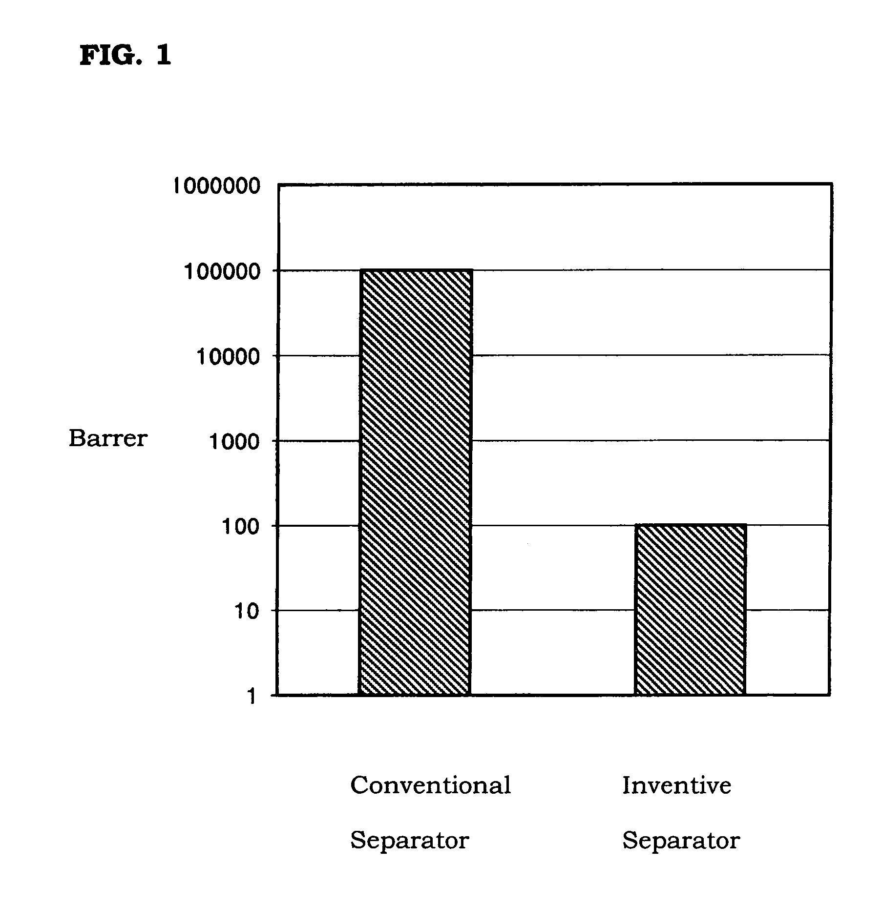
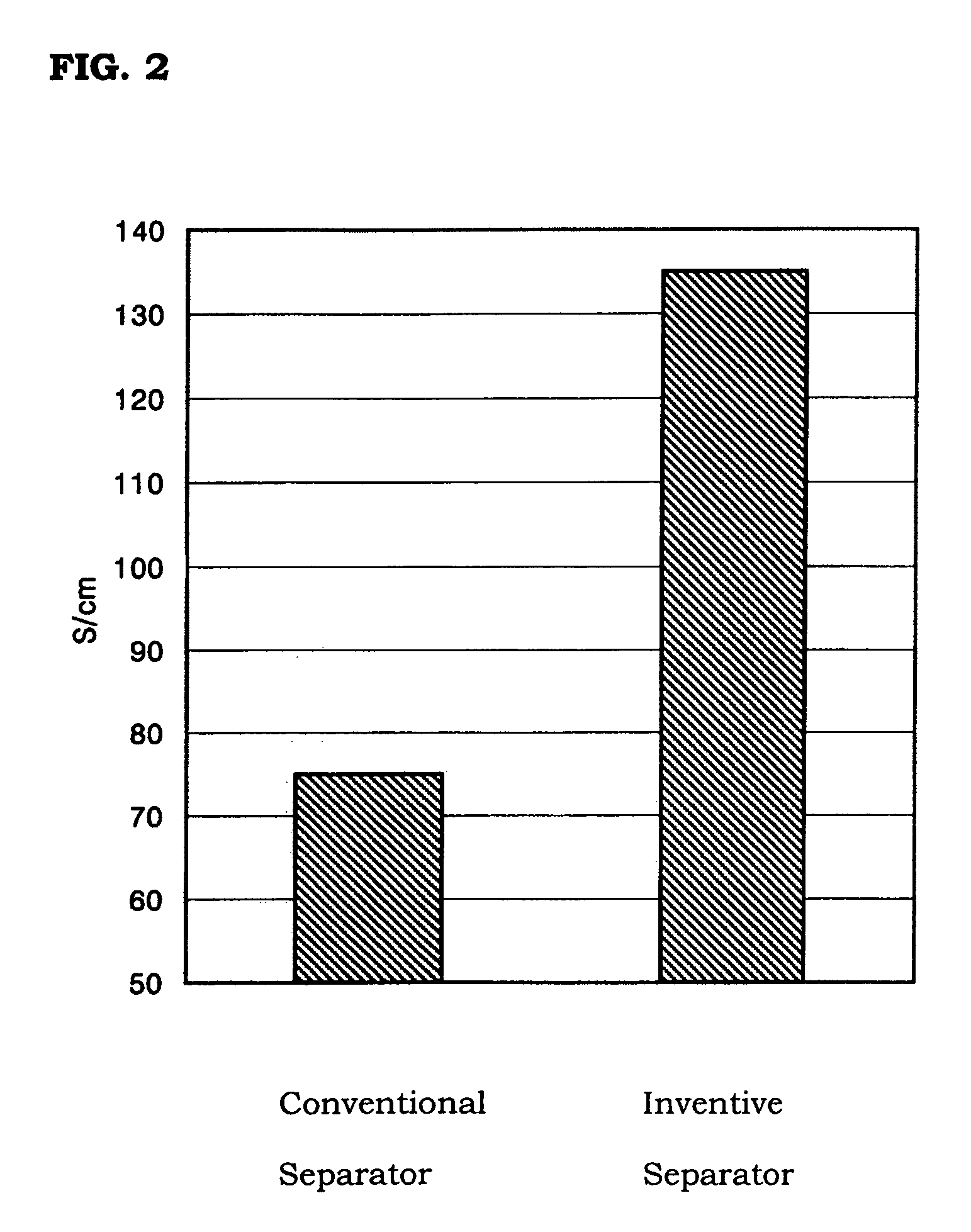
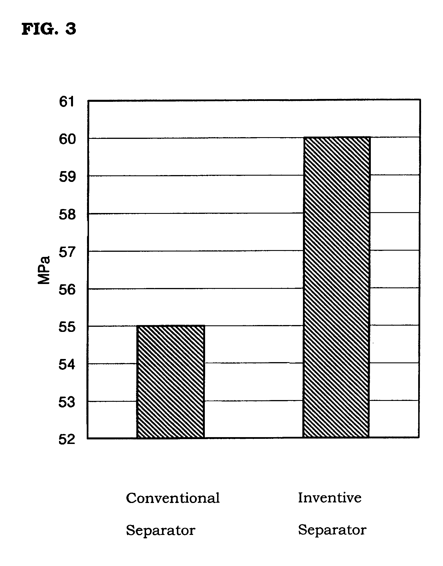
The use of spherical graphite powders or natural graphite powders in the production of fuel cell separators causes problems of low gas permeability, low electrical conductivity and poor strength characteristics.
However, the use of powdery resins degrades the dispersibility of the raw materials, causing heterogeneity in the finished products.
Further, additives for improving the performance of the final products have extremely limited applicability.
As a result, the above-mentioned problems lead to the manufacture of fuel cell stacks with low energy efficiency.

Method used


Image

  • Molding material for fuel cell separator and method for preparing the same
  • Molding material for fuel cell separator and method for preparing the same
  • Molding material for fuel cell separator and method for preparing the same

Examples


example 1

[0031]1,200 parts by weight of a graphite powder, 50 parts by weight of an acid anhydride-based hardener, and 1 part by weight of TPP as a hardening accelerator were added to 100 parts by weight of an epoxy resin. Silane as a binder was added in an amount of 1% by weight, based on the graphite powder. At this time, planar expanded graphite having an average particle diameter of 0.05 mm was used as the graphite powder.

[0032]For homogeneous mixing, the epoxy resin, the hardener, the hardening accelerator and the binder were dissolved in acetone, and then the graphite powder was mixed with the solution using a mixer where both revolution and rotation are simultaneously performed.

[0033]After the addition, the mixture was allowed to stand in a vacuum oven at 50° C. for 3 hours to evaporate the acetone. The dried mixture was then subjected to compression molding to produce a separator (hereinafter, referred to as an “inventive separator”).


PUM

PropertyMeasurementUnit
particle sizeaaaaaaaaaa
particle diameteraaaaaaaaaa

Abstract

Disclosed herein is a method for preparing a molding material for a fuel cell separator by dissolving an epoxy resin, a hardener and other additives in acetone and mixing a planar expanded graphite powder with the solution. Further disclosed are a molding material prepared by the method and a fuel cell separator produced from the molding material. The fuel cell separator shows very low gas permeability, superior electrical conductivity, sufficient strength, and maximized uniformity throughout the overall structure of the finished product.

Description

BACKGROUND OF THE INVENTION[0001]1. Field of the Invention[0002]The present invention relates to a molding material for a fuel cell separator, a method for preparing the material, a fuel cell separator produced from the molding material, and a fuel cell comprising the separator.[0003]A stack, the most important constituent unit of a fuel cell, is composed of a membrane electrode assembly and a bipolar plate called a ‘separator’. The separator is a core element acting as a passage for supplying hydrogen and oxygen to the membrane electrode assembly and transferring electrons generated by a catalytic reaction, and at the same time, playing a role in separating unit cells so as to maintain insulation between the unit cells. For these reasons, fuel cell separators are required to have basic characteristics, such as flexural strength, gas permeability and electrical conductivity, to some extent.[0004]2. Description of the Related Art[0005]Metal separators have been used in conventional f...

Claims


Application Information

Patent Timeline
Patent Type & Authority Patents(United States)
IPC IPC(8): H01M8/00B32B27/04B32B27/20H01M8/02B32B27/38C08K3/04C08L63/00
CPCH01M8/0213H01M8/0221H01M8/0226Y10T428/30Y02E60/50Y10T428/31511Y02P70/50H01M8/02
Inventor LEE, HO SUBKIM, JEONG HEON
Owner HANKOOK TIRE WORLDWIDE
Learn More