Motor drive unit
a motor drive and motor technology, applied in the direction of motor/generator/converter stopper, multiple dynamo-motor starters, motor/generator/converter control, etc., can solve the problem of large motor current detection error, difficulty in wide range of vector control or estimation of rotor position by current detection, etc. problem, to achieve the effect of reducing the interference of switching noise, improving the accuracy of current detection, and low cos
- Summary
- Abstract
- Description
- Claims
- Application Information
AI Technical Summary
Benefits of technology
Problems solved by technology
Method used
Image
Examples
embodiment 1
Preferred Embodiment 1
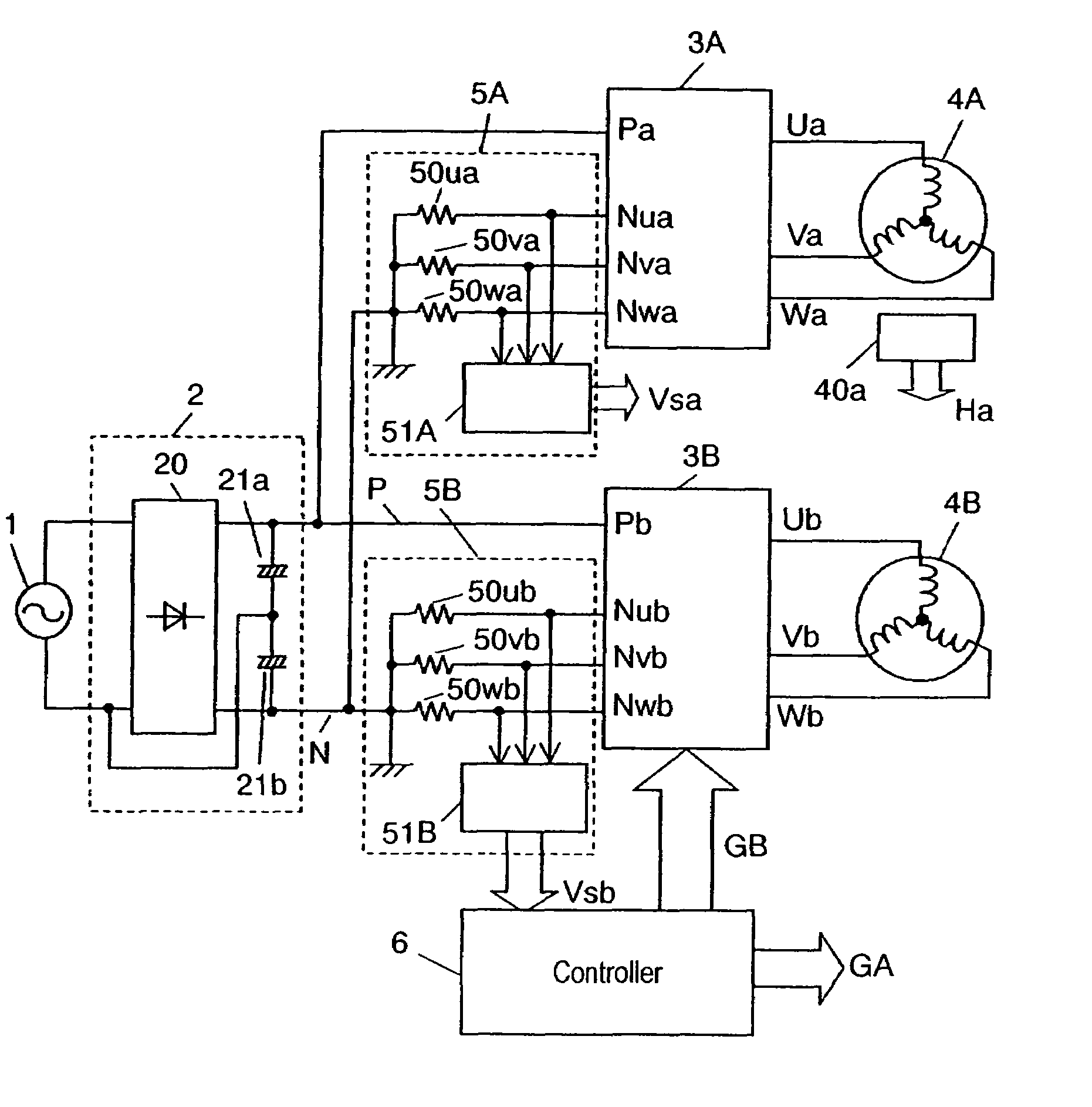
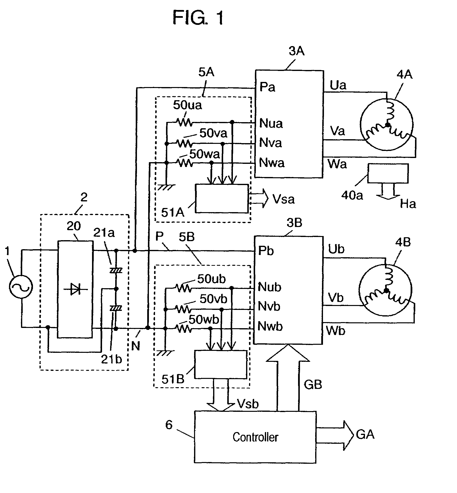
[0018]FIG. 1 indicates a block diagram of the motor drive unit in the preferred embodiment 1 of the present invention. In FIG. 1, AC power is applied from AC power source 1 to DC power source 2 constituted of full-wave rectification circuit 20 and electrolytic capacitors 21a, 21b for conversion into DC power, and the DC power is converted by inverter circuits 3A, 3B into 3-phase AC power to drive motors 4A, 4B. Current detectors 5A, 5B are connected to the negative voltage terminal side of inverter circuits 3A, 3B for detecting the electric current flowing through the respective 3-phase lower arms of inverter circuits 3A, 3B, to thereby detect the output current of inverter circuits 3A, 3B, i.e. electric current in the respective phases of motors 4A, 4B.
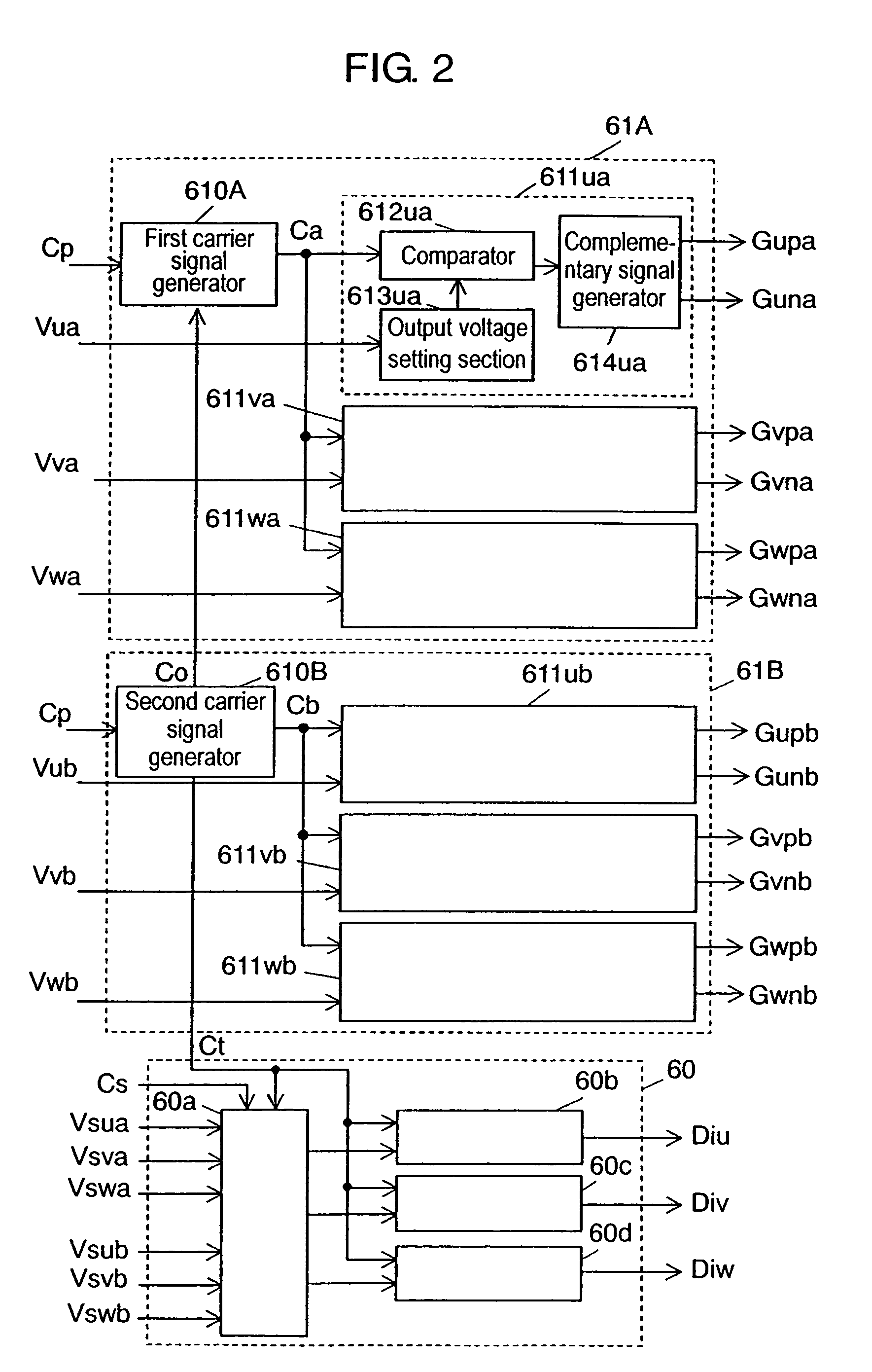
[0019]Controller 6, composed of a high-speed processor such as microcomputer having a plurality of PWM controllers for performing PWM control of inverter circuits 3A, 3B, or digital signal processor (abbreviated...
embodiment 2
Preferred Embodiment 2
[0038]FIG. 6 indicates a timing chart of PWM period and current detection timing of the respective inverter circuits in the preferred embodiment 2, and FIG. 7 shows a flow chart for performing detection of current and vector operation alternately with carrier signals by synchronizing the PWM control of inverter circuits to be driven at once. In FIG. 6 and FIG. 7, first inverter circuit 3A and second inverter circuit 3B are identical in PWM period, and perform timing of detection of current by current detectors 5A, 5B alternately. Other configuration is the same as that in the first preferred embodiment and, therefore, explanation on it will be omitted by putting the same reference numbers.
[0039]Here, explanation will be made, by using FIG. 7, on the flow of performing detection of current and vector operation alternately with carrier signals by synchronizing the PWM control of inverter circuits to be driven at once.
[0040]In FIG. 7, a carrier signal interrupt si...
embodiment 3
Preferred Embodiment 3
[0044]FIG. 8 indicates a timing chart of PWM period and current detection timing of the respective inverter circuits in the third preferred embodiment. FIG. 8 shows a timing of detection of current in the case where first inverter circuit 3A and second inverter circuit 3B are identical in PWM period, and that their PWM periods are shifted by 180 degree from each other. Other configuration is the same as that in the first preferred embodiment and, therefore, explanation on it will be omitted by putting the same reference numbers.
[0045]By equalizing the count-up time and the count-down time of triangular wave carrier signals, it becomes possible to realize a phase shift of 180 degree easily, enabling PWM control with 180 degree phase shift. During continuity of the lower arm transistor of first inverter circuit 3A (Gna high), continuity is established in the upper arm transistor of second inverter circuit 3B (Gpb high), while, during continuity of the lower arm t...
PUM
 Abstract
Description
Claims
Application Information
 - R&D
- Intellectual Property
- Life Sciences
- Materials
- Tech Scout
- Unparalleled Data Quality
- Higher Quality Content
- 60% Fewer Hallucinations
Browse by: Latest US Patents, China's latest patents, Technical Efficacy Thesaurus, Application Domain, Technology Topic, Popular Technical Reports.
© 2025 PatSnap. All rights reserved.Legal|Privacy policy|Modern Slavery Act Transparency Statement|Sitemap|About US| Contact US: help@patsnap.com


