
Level shift circuit

a level shift and circuit technology, applied in the direction of electrical equipment, pulse automatic control, baseband system details, etc., can solve the problems of large amount of power and require a complicated circuit, and achieve the effects of low power dissipation, high reliability, and high performan

Active Publication Date: 2008-12-16
REALTEK SEMICON CORP
View PDF16 Cites 2 Cited by
  • Summary
  • Abstract
  • Description
  • Claims
  • Application Information

AI Technical Summary

Benefits of technology

The present invention provides a level shift circuit with high performance, reliability, low power dissipation, simplified realization, and low cost. The circuit is designed for driving an audio device and includes a first voltage level transfer unit, a second voltage level transfer unit, and a control block circuit. The first and second input signals are inversed. The technical effect of this invention is to provide a more efficient and reliable level shift circuit for driving audio devices.

Problems solved by technology

The level shift circuit using this method to generate levels will consume a large amount of power and require a complicated circuit to ensure the reliability and performance.

Method used


Image

  • Level shift circuit
  • Level shift circuit
  • Level shift circuit

Examples


first embodiment

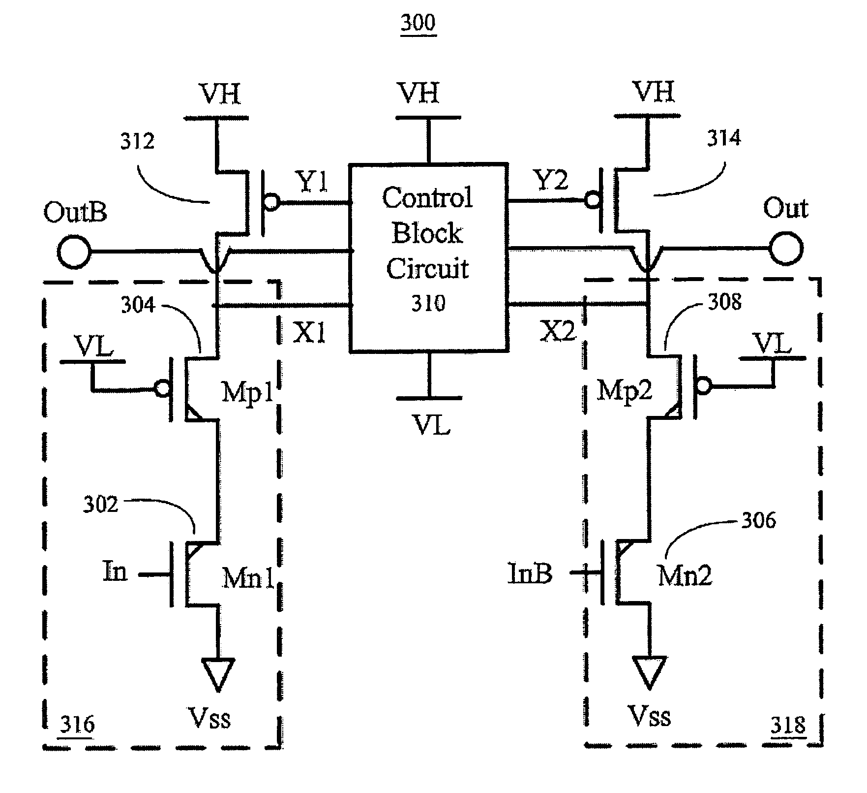
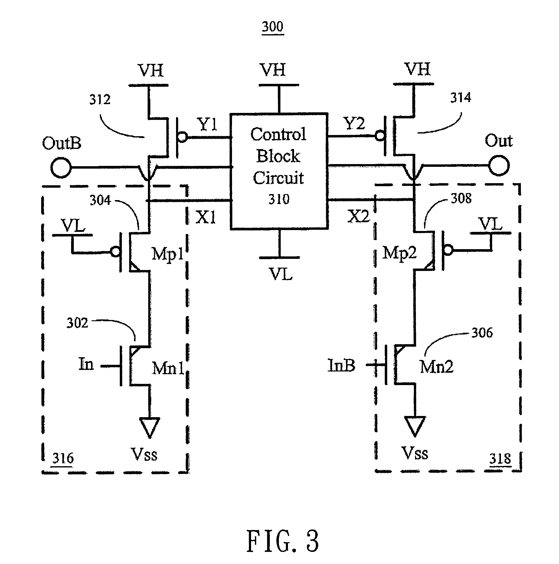
[0019]FIG. 3 is a circuit diagram of a level shift circuit 300 according to the present invention. The level shift circuit 300 comprises a first voltage level transfer unit 316, a second voltage level transfer unit 318, a control block circuit 310, a first PMOS pull-up transistor 312 and a second PMOS pull-up transistor 314. The first voltage level transfer unit 316 further comprises a NMOS transistor 302 and a PMOS transistor 304, wherein the gate of NMOS transistor 302 receives a first input signal which is operated in first voltage level (Vdd and Vss), the source of the NMOS transistor 302 is coupled to the supply voltage Vss, and the drain and gate of PMOS transistor 304 are respectively coupled to the NMOS transistor 302 and supply voltage VL for outputting the level transferred control signal X1 (operated in VH and VL level). On the other hand, the second voltage level transfer unit 318 comprises NMOS transistor 306 and PMOS transistor 308, wherein the gate of NMOS transistor ...

second embodiment

[0023]FIG. 6 is a circuit diagram of a level shift circuit 600 according to the present invention. The level shift circuit 600 comprises a first voltage level transfer unit 616, a second voltage level transfer unit 618, a control block circuit 610, a first NMOS pull-down transistor 612 and a second NMOS pull-down transistor 614. The first voltage level transfer unit 616 further comprises PMOS transistor 602 and NMOS transistor 604, wherein the gate of PMOS transistor 602 receives a first input signal which is operated in first voltage level (Vdd and Vss), the source of the PMOS transistor 602 is coupled to the supply voltage Vdd, and the drain and gate of NMOS transistor 604 are respectively coupled to the PMOS transistor 602 and supply voltage VH for outputting the level transferred control signal X1 (operated in VH and VL level). On the other hand, the second voltage level transfer unit 618 comprises PMOS transistor 606 and NMOS transistor 608, wherein the gate of PMOS transistor ...


PUM


Abstract

In many high voltage circuits, it often needs to shift the logic voltage level to keep the circuit normal operation. In the class-D amplifier circuitry, it needs to shift the voltage level of pulse width modulation (PWM) signal to control the connecting of different power switches. In other applications, such as a driver to drive amplifier of an audio device, it also needs a level shift circuit to maintain the circuitry in normal voltage operation. Therefore, this invention is to provide a novel level shift circuit with high performance, low cost and low power dissipation characteristics.

Description

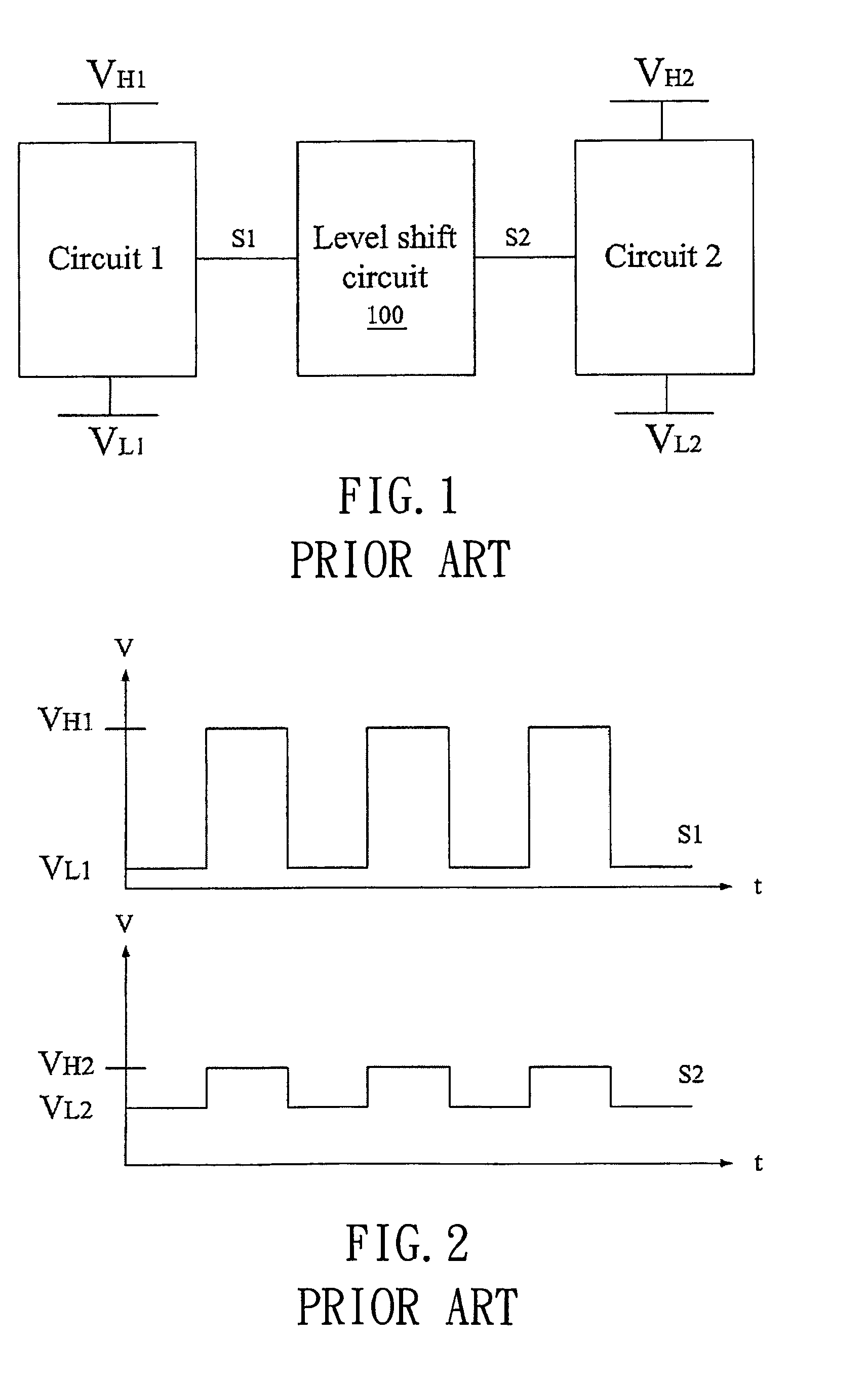
BACKGROUND OF THE INVENTION[0001]1. Field of the Invention[0002]The present invention relates to a level shift circuit, and more particularly, to the level shift circuit that has a low power dissipation and is realized in a more simplified way.[0003]2. Description of Related Art[0004]As shown in FIG. 1, one integrated circuit (IC) could exist different supply voltages for different applications, a level shift circuit 100 is required between two circuitries with different supply voltages to adjust the level of logic signals so as to maintain the normal operation of the circuitry. FIG. 2 is a diagram showing the signal relation between an input signal S1 and an output signal S2 of the level shift circuit 100 in FIG. 1. As shown in FIG. 2, after the output signal S2 passes the level shift circuit 100, its logic value does not change, but its voltage level is different. The voltage level of VH1 is shifted to the voltage level of VH2, and the voltage level of VL1 is shifted to the Voltag...

Claims


Application Information

Patent Timeline
Patent Type & Authority Patents(United States)
IPC IPC(8): H03L5/00
CPCH04L25/0264
Inventor WANG, TZE-CHIEN
Owner REALTEK SEMICON CORP
Learn More