
Fetal oximetry system and sensor

a technology sensor, which is applied in the field of optical measurement devices, can solve the problems of affecting the reading, affecting the accuracy of the reading, and the inability of current pulse oximeters to achieve clinical acceptance as primary indicators of fetal oxygen saturation level, etc., and achieves the effect of improving accuracy and usable signal tim

Inactive Publication Date: 2008-12-23
RIC INVESTMENTS LLC
View PDF33 Cites 67 Cited by
  • Summary
  • Abstract
  • Description
  • Claims
  • Application Information

AI Technical Summary

Benefits of technology

"The present invention provides an optical measuring device with improved accuracy and usable signal time. This is achieved by utilizing multiple optical measurement paths through a tissue, which allows for independent measurements that are affected by optical path dependent factors. The device produces at least two distinct sets of wavelengths of light, which are selectively weighted ratios of the light measured from the paths. The sensor includes light emitters and detectors disposed along multiple optical paths and the light is carried through the paths by light transmitting fibers. The device also includes a mechanism for selectively coupling the sensor to an insertion rod and an introducer tube to maintain the sensor in a safe position during insertion and application. The circuit connector includes features such as a stiffening member, shielding layer, and slit to increase flexibility and minimize bending."

Problems solved by technology

However, current pulse oximeters have generally failed to obtain clinical acceptance as a primary indicator of fetal oxygen saturation level.
One possible reason is that the non-invasive nature of most pulse oximeters leaves them susceptible to motion artifact problems on the part of the mother and the unborn baby.
During contractions, the probe could be dislodged or the variation in pressure of the contraction itself might alter the optical path and upset the reading.
Obviously, such a probe would become dislodged during the final stages of delivery.
Other concerns with pulse oximeters for monitoring fetal oxygen saturation level are poor signal quality because of poor probe contacts, merconium staining (fetal bowel movement), vernix (a cheesy fetal skin covering), hair, and caput formation (swelling in the scalp).
For example, among other things, a variation typically occurs between SpO2 and SaO2, thereby degrading the accuracy of the oximeter.
In addition, the use of pulse oximeters to monitor fetal oxygen saturation level presents other difficulties.
For example, the caregiver placing the oximetry sensor on the unborn baby must do so while the baby remains in the mother's womb, thereby limiting the caregiver's view and maneuverability in placing the sensor on the baby.
Furthermore, the sensor provided on the unborn baby can only be used once.
Many of the above problems related to the optical measurement of oxygen saturation are also present in other optical measurement applications, such as optical measurement of blood glucose, bilirubin, and hemoglobin.

Method used


Image

  • Fetal oximetry system and sensor
  • Fetal oximetry system and sensor
  • Fetal oximetry system and sensor

Examples


Embodiment Construction

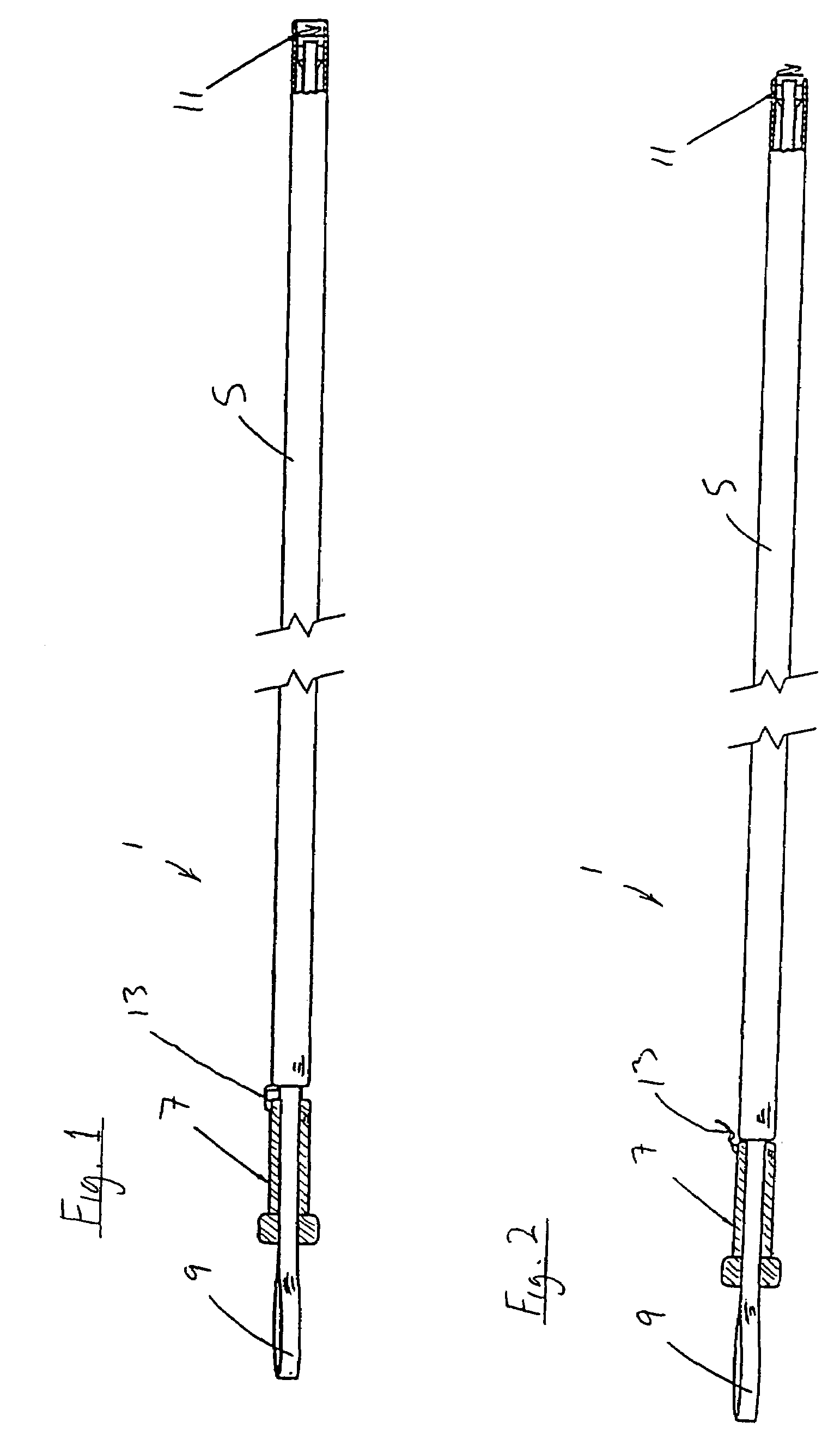
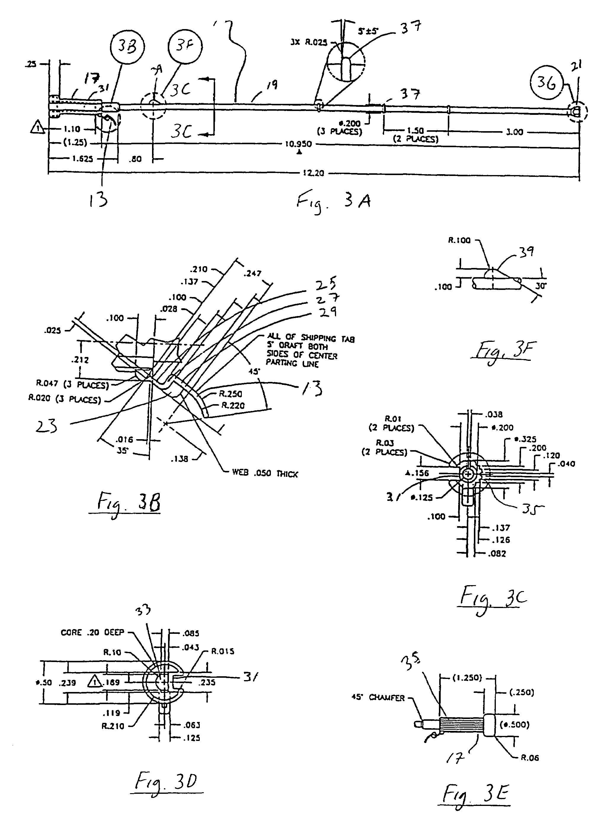
[0042]The following is a detailed description of an example of components and assembly procedures for manufacturing a preferred embodiment of a fetal pulse oximetry sensor system according to the invention. Numerous aspects of the invention are set forth with respect to specific parts of the sensor system and their assembly procedures. This description should be considered as illustrative and not limiting. FIGS. 2 and 3 are elevational views showing a sensor system 1 according to the principles of the present invention. Sensor system 1 includes an introducer tube 5, an insertion rod 7, a circuit connector 9, and a sensor 11. Each of these components of sensor system 1 are hereinafter described in detail, along with related assembly procedures.

I. Introducer Tube

[0043]Introducer tube 5 is a length of hollow tubing cut to a precut length, for example, 11.05 inches. Preferably, the tubing is made of a biologically compatible plastic, such as polypropylene or polycarbonate, and has round...


PUM


Abstract

An optical measuring device having multiple optical paths between one or more light emitters and one or more light detectors and / or providing at least two sets of wavelength of light along at least one path, with a final measurement being produced as a combination of measurements of the sets of wavelengths of light taken along one or more of the optical paths. Features that contribute to increased safety and ease of use include providing (1) a receiving cavity in a proximal end of an insertion rod that holds a free end of a circuit connector to keep it from becoming tangled or snagged, (2) a mechanism to keep the sensor within an introducer tube during storage and insertion and to expose a portion of the sensor only when the sensor is applied to the unborn baby, (3) a tab on the insertion rod to prevent the circuit connector from becoming tangled or snagged within the introducer tube, (4) a rotating feature whereby if a torque applied on the sensor exceeds a first predetermined amount, the sensor rotates, and a disengaging feature whereby the sensor detaches from insertion rod if a pull-off force exceeds a second predetermined amount, the rotating and disengaging features being independent of one another, (5) a circuit connector that includes at least one of the following features: (a) a stiffening member provided at the proximal end to minimize bending, (b) a shielding layer, and (c) at least one slit to increase the flexibility of the circuit connector, and (6) an interface that includes an identification element that is detected by an external circuit only if the circuit connector is connected to the interface. The present invention also pertains to a method of manufacturing a needle that is used in an invasive sensor, and preferably for fetal monitoring, that provides features not heretofore available in conventional sensors.

Description

[0001]This application is a divisional application pursuant to 35 U.S.C. §120 of earlier filed U.S. patent application Ser. No. 09 / 581,122 filed Jan. 14, 2002, now abandoned, which was a national phase application pursuant to the Patent Cooperation Treaty, of International Application Serial No. PCT / US98 / 12394, filed Jun. 15, 1998, which claimed priority to Provisional Application Ser. No. 60 / 050,958, filed Jun. 17, 1997.TECHNICAL FIELD[0002]The present invention relates generally to optical measurement devices, and more particularly to fetal oximetry systems and sensors with improved accuracy, reliability, safety and ease of use. The invention further relates to a method of making and using such devices.BACKGROUND ART[0003]Oximetry is based on the principle that the color of blood is related to the oxygen saturation level (SaO2) in the blood. For example, as blood deoxygenates, skin loses its pinkish appearance and takes on more of a bluish tint. Current pulse oximeters operate by ...

Claims


Application Information

Patent Timeline
Patent Type & Authority Patents(United States)
IPC IPC(8): A61B5/1455A61B5/145A61B5/00A61B5/1464
CPCA61B5/14542A61B5/1464A61B5/6848A61B5/6882
Inventor CUTLER, CHRISTOPHER A.WALLACE, WILLIAM D.SMITH, STEVEN R.MCGRAW, DANIEL J.TU, NICKMONTAGNOLI, CLIFFORD G.BANKS, TRENT W.
Owner RIC INVESTMENTS LLC
Learn More