Engine with an active mono-energy and/or bi-energy chamber with compressed air and/or additional energy and thermodynamic cycle thereof

a mono-energy, compressed air technology, applied in the field of engines, can solve the problems of low flow rate, heavy, poorly-performing devices, easy to freeze, etc., and achieve the effect of increasing the temperature and/or pressure of the air

Active Publication Date: 2008-12-30
MDI MOTOR DEV INT SA
View PDF9 Cites 68 Cited by
  • Summary
  • Abstract
  • Description
  • Claims
  • Application Information

AI Technical Summary

Benefits of technology

[0030]It its bi-energy application according to the invention and in supplementary fuel mode, the compressed air contained in the work capacity is heated by supplementary energy in a thermal heater. The arrangement enables the quantity of usable and available energy to be increased due to the fact that before being introduced into the active chamber the compressed air rises in temperature and increases its pressure and / or volume enabling increases in performance and / or autonomy. The use of a thermal heater has the advantage of enabling clean continuous combustion to be used which can be catalyzed or depolluted by any existing means in order to obtain minimal polluting emissions.
[0031]A thermal heater can use fossil fuels such as petrol, diesel or vehicle LPG, bio fuels or alcohols—ethanol, methanol—thus achieving bi-energy operation with external combustion where a burner is used to increase the temperature.
[0042]When the engine piston is stopped at top dead centre: admission of a charge into the active chamber producing work by increasing its volume,
[0048]During operation in compressed air mode, on a vehicle running in an urban location operating without pollution for example, only the pressure of the compressed air stored in the high pressure reservoir is used; in bi-energy operation in supplementary energy mode (fossil or other), on a vehicle running on the open road with minimal pollution for example, the heating of the work capacity is then required to increase the temperature of the air passing through it and consequently its usable volume and / or pressure thus giving better performance and / or autonomy.

Problems solved by technology

The well-known conventional pressure reducing valves using diaphragms and springs have very low flow rates and their use for this application requires very heavy poorly-performing devices; furthermore, they are very susceptible to freezing due to the humidity of the air chilled during the pressure drop.
The filling up of the chamber is always detrimental to the general efficiency in the operation of these “pressure reduction” engines.

Method used


Image

  • Engine with an active mono-energy and/or bi-energy chamber with compressed air and/or additional energy and thermodynamic cycle thereof
  • Engine with an active mono-energy and/or bi-energy chamber with compressed air and/or additional energy and thermodynamic cycle thereof
  • Engine with an active mono-energy and/or bi-energy chamber with compressed air and/or additional energy and thermodynamic cycle thereof

Examples


Embodiment Construction

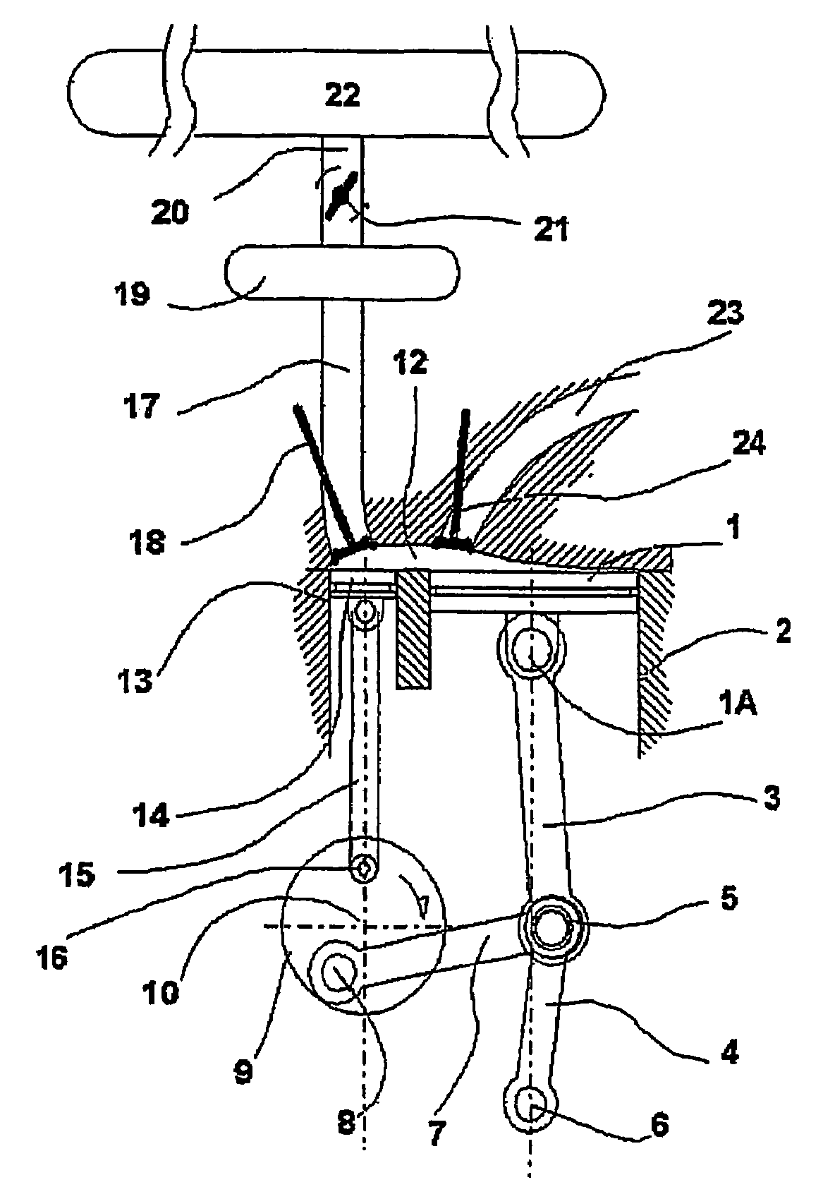
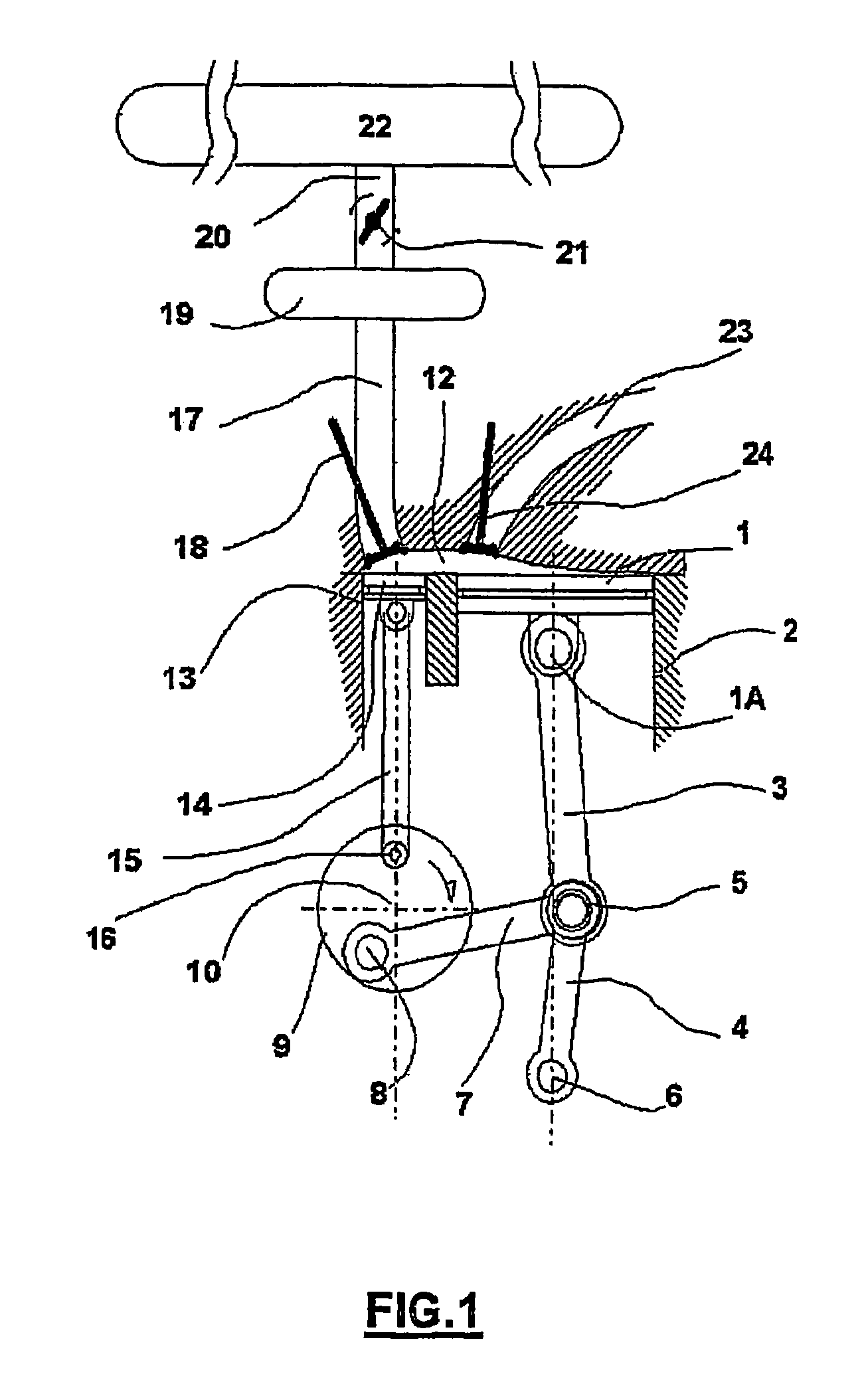
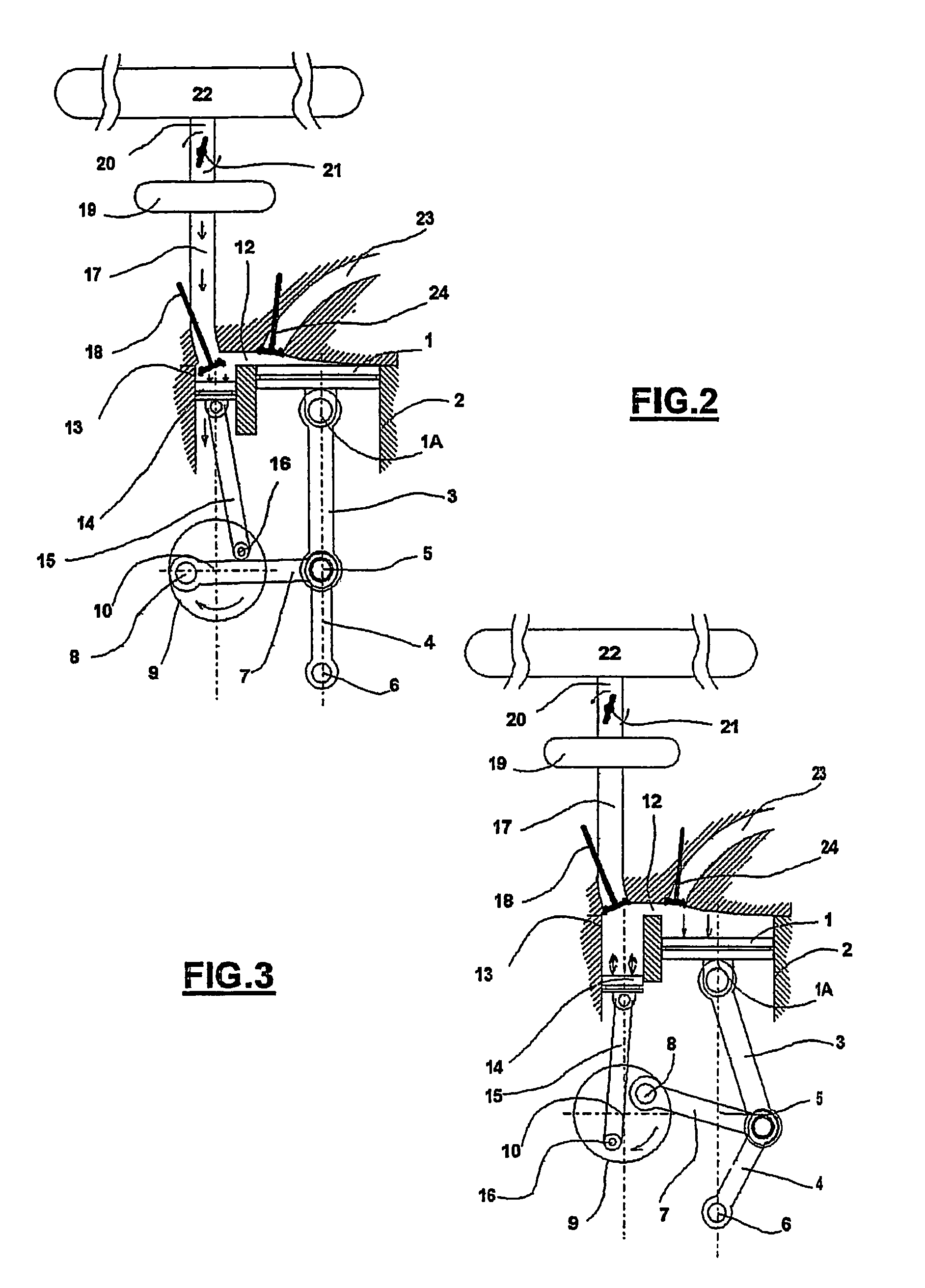
[0077]FIG. 1 represents an active chamber engine according to the invention which shows the engine cylinder in which piston 1 slides (represented at its top dead centre), sliding in cylinder 2 which is controlled by a pressure lever. Piston 1 is connected by its pin to the free end 1A of a pressure lever made up of arm 3 articulated on pin 5 common to another arm 4 fixed oscillating on immobile pin 6. On pin 5 common to arms 3 and 4 a control connecting rod 7 is connected to crankpin 8 of crank 9 turning on its axis 10. When the crank rotates, the control connecting rod 7 exercises a force on common pin 5 of arms 3 and 4 of the pressure lever thus moving piston 1 along the axis of cylinder 2 and transmits in return the forces exercised on piston 1 during the engine stroke to crank 9 thus causing it to rotate. The engine cylinder is connected via passage 12 in its upper part with active chamber cylinder 13 in which piston 14 (known as the pressure piston) slides connected by connecti...


PUM


Abstract

An engine uses a top dead center piston stop device. It is fed by compressed air, via a working capacity, which, in the bi-energy version, includes a device for heating the air supplied by additional energy. The active expansion chamber consists of a variable volume or charge piston sliding in a cylinder, coupled to a space above the engine piston via a passage. When stoped at upper dead center, the pressurized air is admitted into the expansion chamber with the smallest volume thereof and, under the effect of thrust, increases the volume thereof by producing work; the expansion chamber is then kept at a maximum volume during expansion of the engine cylinder driving back the engine piston in its downward stroke, providing work of its own. During exhaust, the two pistons travel in an upward stroke and simultaneously reach top dead center in order to resume a new cycle.

Description

BACKGROUND OF THE INVENTION[0001]1. Field of the Invention[0002]The invention concerns an engine which runs notably on compressed air or any other gas, and more particularly using a piston travel control device which stops the piston at top dead centre for a period of time together with a device for recovering ambient thermal energy which can operate in mono- or bi-energy mode.[0003]2. Description of the Related Art[0004]The author has registered numerous patents concerning drive systems along with their installations using compressed air for totally clean operation in urban and suburban locations:[0005]WO 96 / 27737 WO 97 / 00655[0006]WO 97 / 48884 WO 98 / 12062 WO 98 / 15440[0007]WO 98 / 32963 WO 99 / 37885 WO 99 / 37885[0008]For the implementation of these inventions, he has also described in his patent application WO 99 / 63206, to which reference should be made, an engine piston travel control device and process which enables the piston to be stopped at top dead centre, a process also described ...

Claims


Application Information

Patent Timeline
Patent Type & Authority Patents(United States)
IPC IPC(8): F02C5/00F01B9/02F01B17/02F02B41/00F02B75/32
CPCF01B17/02F02B75/32F02B41/00F01B19/02F01B9/02
Inventor NEGRE, GUYNEGRE, CYRIL
Owner MDI MOTOR DEV INT SA
Why Eureka
Try Eureka