
Non-circular-orbit detection method and apparatus

a non-circular orbit and detection method technology, applied in calibration apparatuses, instruments, tomography, etc., can solve the problems of large probability of error, sharp changes in resolution during operation, and time required to move the detector to the standard position

Active Publication Date: 2008-12-30
SIEMENS MEDICAL SOLUTIONS USA INC
View PDF9 Cites 25 Cited by
  • Summary
  • Abstract
  • Description
  • Claims
  • Application Information

AI Technical Summary

Benefits of technology

[0020]The preferred embodiments of the present invention can significantly improve upon existing methods and / or apparatuses.
[0023]According to other embodiments of the invention, an orbital-detector apparatus is provided that includes: a) a first detector element to detect inside a patient; b) a first sensor element to sense patient proximity to the first detector element; c) a second detector element to detect inside the patient; d) a second sensor element to sense patient proximity to the second detector element; e) a first carrier mechanism configured to move the first detector element in a first direction from a position distal to the patient to a position adjacent to the patient based on an output of the first sensor element; f) a second carrier mechanism configured to move the second detector element in a second direction from a position distal to the patient to a position proximate to the patient based on an output of the second sensor element; g) a control unit configured to determine an orbital path of at least one of the first detector element and second detector element around the patient based upon the position adjacent to the patient in part e) and the position adjacent to the patient in part f). Preferably, the apparatus varies a radius of the orbital path to reduce a distance of the first and second detector elements from the patient. Preferably, at least one of the first detector element and the second detector element includes a parallel-hole collimated detector.

Problems solved by technology

One disadvantage of this type of method is the time required to move the detector to the standard position.
In addition, because the pre-programming is performed manually, the likelihood of error is large.
Among other things, this method has disadvantages related to the potential of creating sharp changes in the resolution during operation.
In addition, the quality of the image deconstruction can be degraded by sharp jumps in image resolution from view to view.
Among other problems, a pre-scan adds a significant amount of time.

Method used


Image

  • Non-circular-orbit detection method and apparatus
  • Non-circular-orbit detection method and apparatus
  • Non-circular-orbit detection method and apparatus

Examples


Embodiment Construction

[0027]While the present invention may be embodied in many different forms, a number of illustrative embodiments are described herein with the understanding that the present disclosure is to be considered as providing examples of the principles of the invention and such examples are not intended to limit the invention to preferred embodiments described herein and / or illustrated herein.

[0028]In some preferred embodiments of the invention, the system can achieve advantages beyond prior methods while avoiding disadvantages therein. The preferred embodiments of the invention can be employed in a variety of environments and can, e.g., be used in whole body, cardiac and / or general SPECT studies and / or can be useful in, e.g., various general purpose, cardiology, oncology and / or neurology studies.

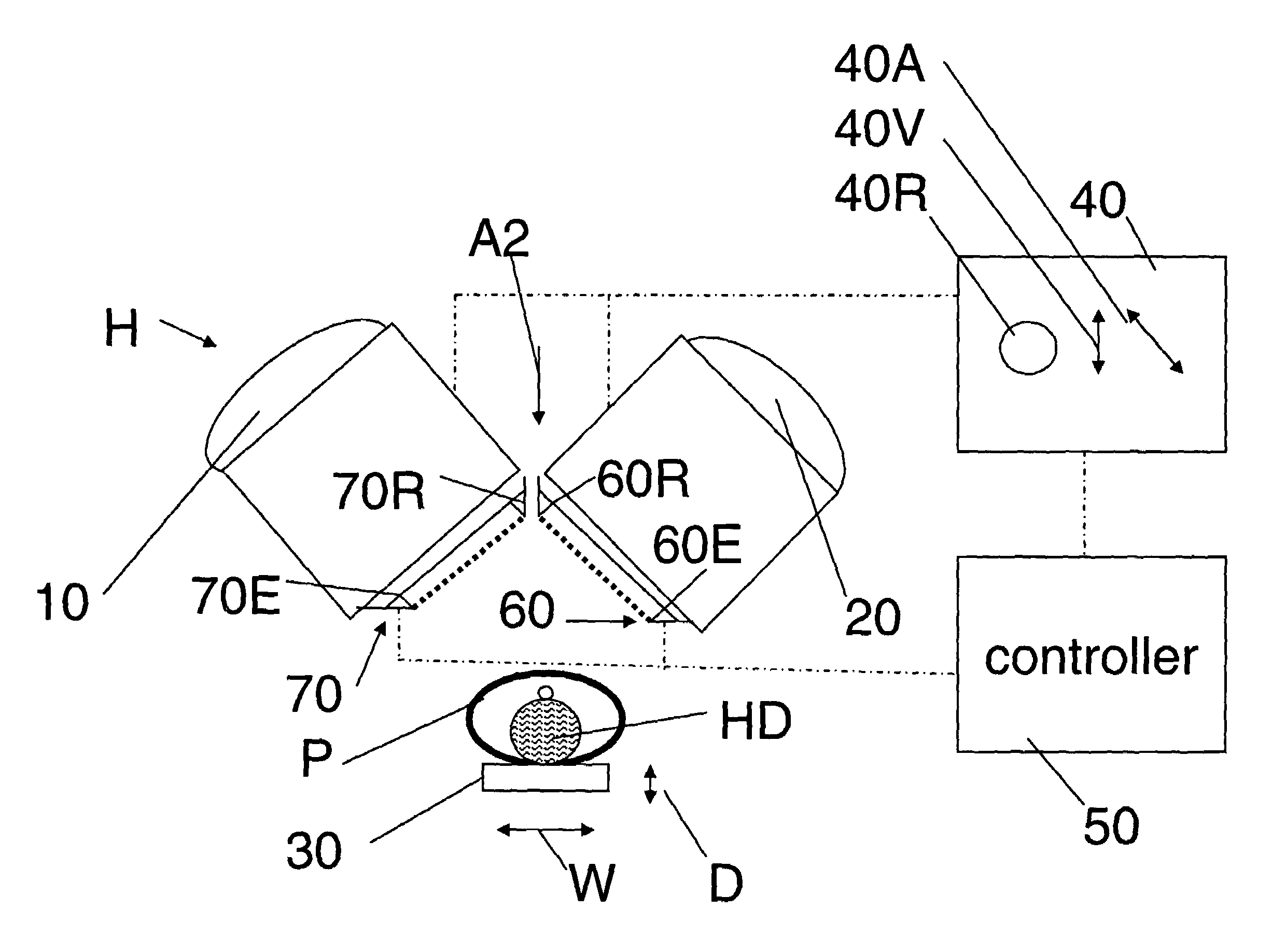
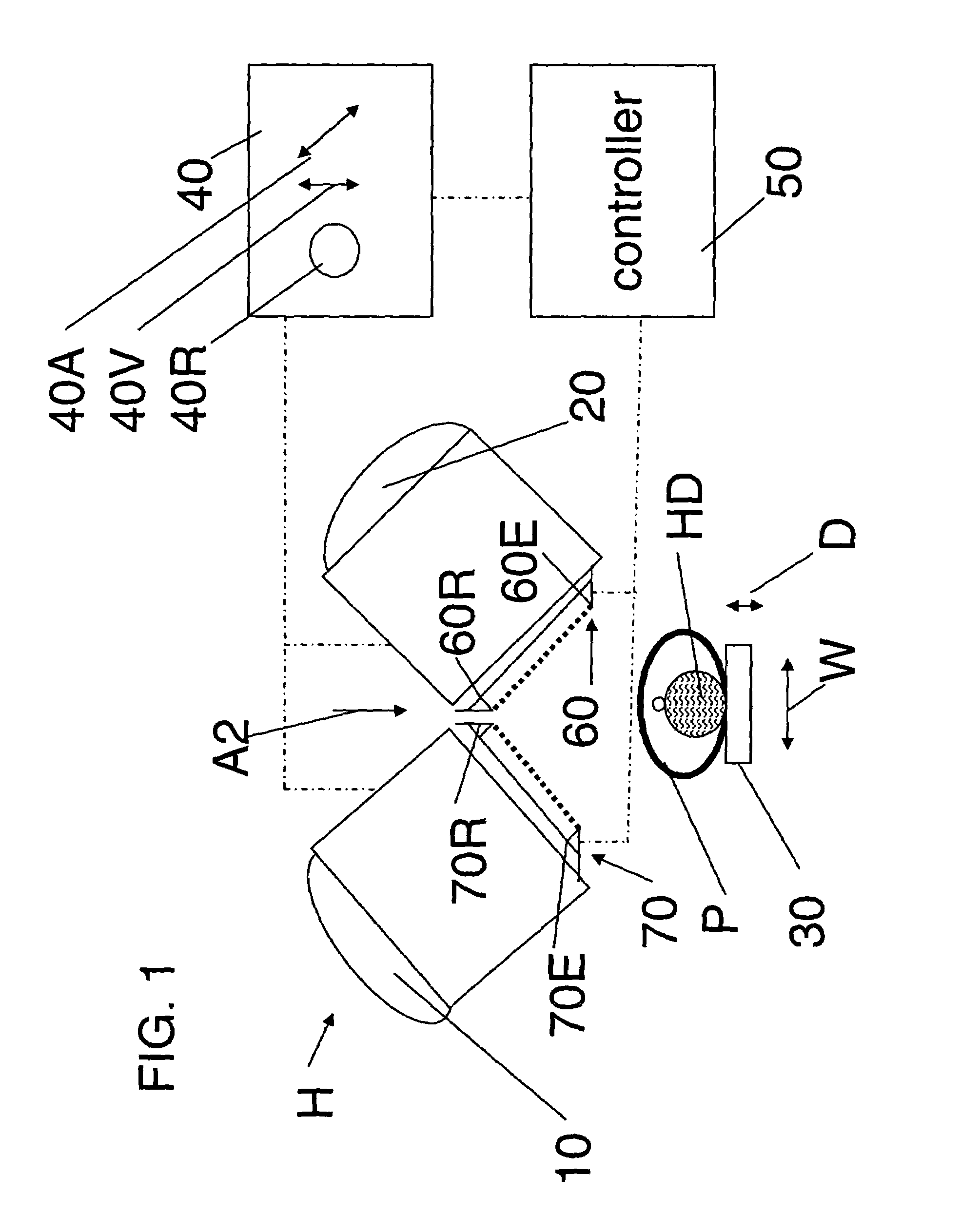
[0029]With reference to FIG. 1, some illustrative embodiments of the invention include: a first detector element 10; a second detector element 20; a support 30 upon which a patient P can rest; a car...


PUM


Abstract

A non-circular-orbit detection method and apparatus is disclosed. In some embodiments, the method includes: locating first and second detectors, displaced with respect to one another, a distance from a patient; moving the first and second detectors in a direction towards the patient until a first sensor senses a first point of the patient at a first sensing position; moving the first and second detectors in a second direction from the first sensing position until a second sensor senses a second point of the patient at a second sensing position; and moving the first and second detectors in a non-circular-orbit around the patient. Preferably, the method includes determining the non-circular-orbit based on, among other things, locations of the first point and the second point.

Description

BACKGROUND[0001]1. Field of the Invention:[0002]The present invention relates to methods and apparatuses for scanning a body and preferred embodiments relate, more particularly, to methods and apparatuses for determining a non-circular-orbit for scanning a patient.[0003]2. Discussion of the Background:[0004]In some existing systems, gamma cameras are used to form tomographic images of a patient during a nuclear medicine study. In, for example, single photon emission computed tomography (SPECT) systems of the transaxial rotational camera type, a scanning gamma camera head can rotate around a region of the patient to be scanned. Typically, this rotation is in a plane generally orthogonal to a cranial-caudal axis of a patient and results in the imaging of a cross-sectional slice of the patient's body.[0005]In general, for certain detectors, such as, e.g., parallel hole collimated detectors, resolution decreases with distance so that keeping the detector close to the patient can improve...

Claims


Application Information

Patent Timeline
Patent Type & Authority Patents(United States)
IPC IPC(8): G12B13/00G01B11/14G01T1/164
CPCG01T1/1644A61B6/037A61B6/027
Inventor PAWLAK, JOHN THOMASPERRONE, ANTHONY
Owner SIEMENS MEDICAL SOLUTIONS USA INC
Learn More