
Curved-slab maximum intensity projections

a projection and maximum intensity technology, applied in the field of medical imaging, can solve the problems of reduced contrast between vessels and background, difficult to discern three-dimensional vascular anatomy, apparent vessel narrowing, etc., and achieve the effect of reducing background intensity, reducing apparent vessel narrowing, and increasing overall arterial contras

Inactive Publication Date: 2008-12-30
THE BOARD OF TRUSTEES OF THE LELAND STANFORD JUNIOR UNIV
View PDF11 Cites 4 Cited by
  • Summary
  • Abstract
  • Description
  • Claims
  • Application Information

AI Technical Summary

Benefits of technology

[0013]The advantage of the present invention is that the curved-slab MIP increases overall arterial contrast to background compared with rectangular-slab MIP as a result of reduced background intensity and exhibits a corresponding reduction in apparent vessel narrowing that may reduce overestimation of stenoses and disappearance of low-intensity vessels. The present method allows multiple vessels to be included in each image without including excessive amounts of soft tissue and high-attenuating bone. This method has the potential to reduce the time required to assess vasculature with MIPs.
[0014]The objectives and advantages of the present invention will be understood by reading the following detailed description in conjunction with the drawings, in which:
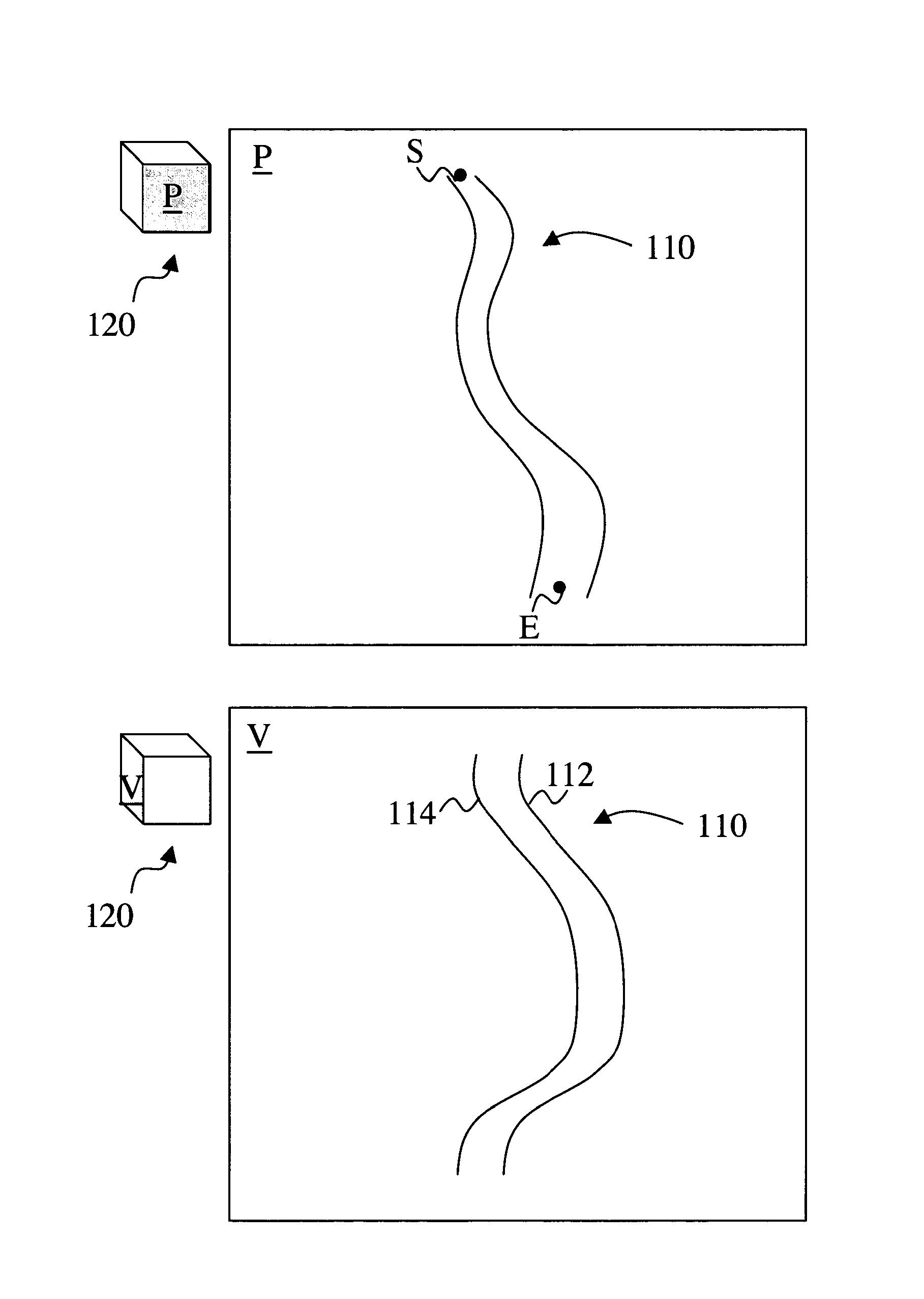
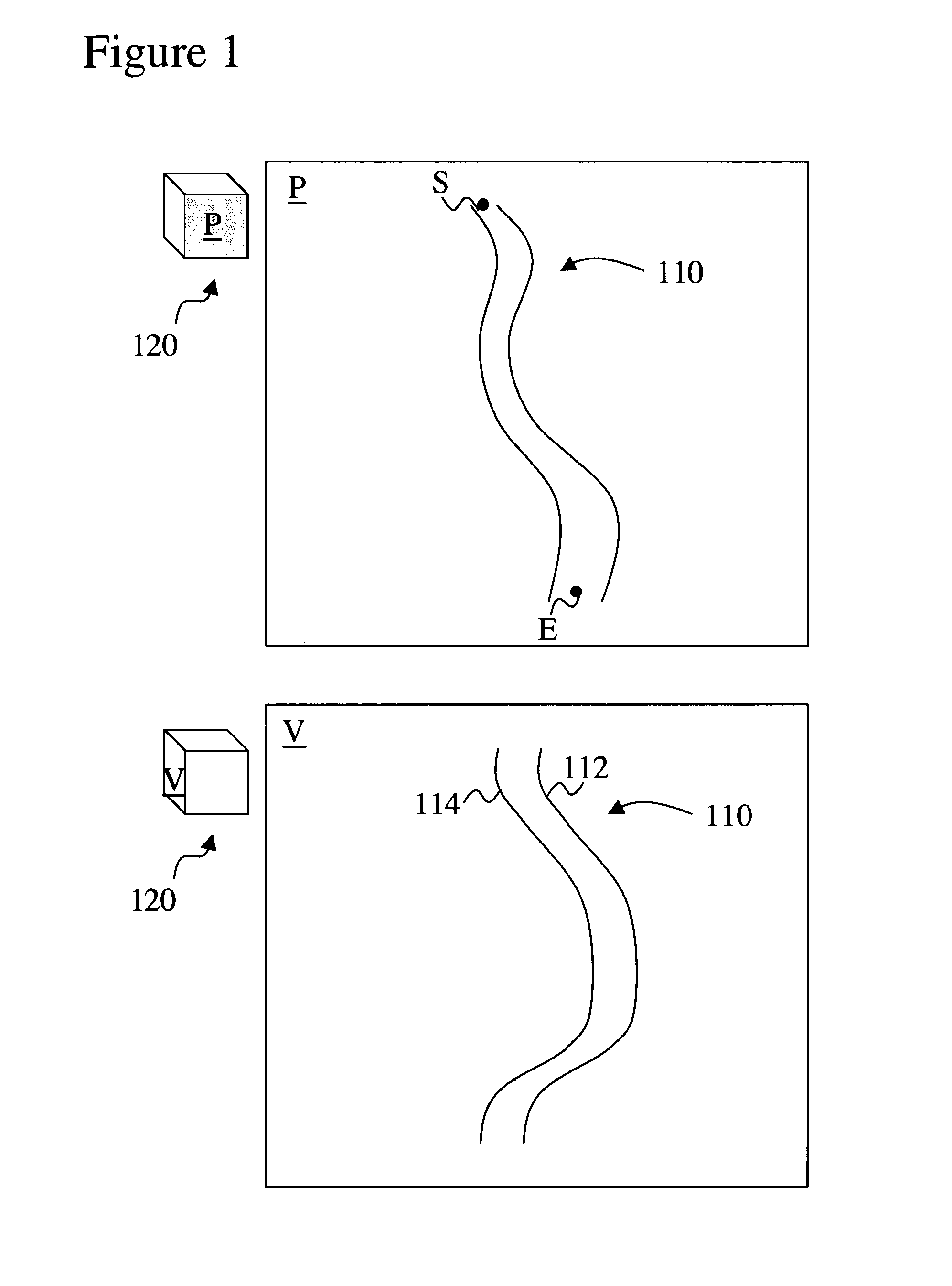
[0015]FIG. 1 shows an example of a projection plane selecting a start point and end point of a vessel according to the present invention;
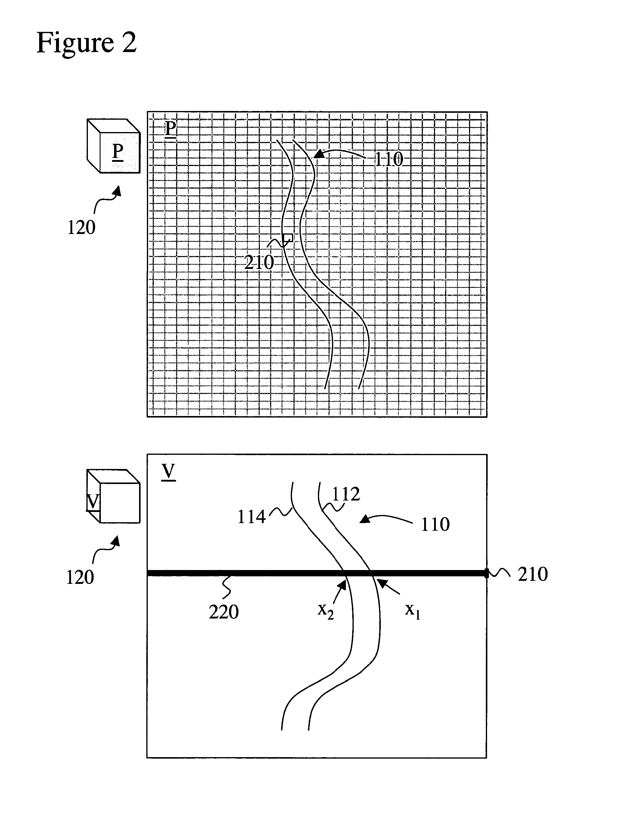
[0016]FIG. 2 shows an example of determining a boundary pair for a pixel according to the present invention;
[0017]FIG. 3 shows an example of fine-tuning or re-determining a boundary pair according to the present invention;
[0018]FIG. 4 shows an example of determining and smoothing a curved slab define for a vessel according to the present invention;

Problems solved by technology

In addition, three-dimensional vascular anatomy is difficult to discern when only cross-sectional images are used.
Although MIPs exhibit an increased contrast-to-noise ratio compared with that of source images, predominantly as a result of decreased noise, the reduced contrast between vessels and background can result in artifacts.
The edges of larger vessels, which are less intense than the vessel center because of volume averaging, may be obscured, which leads to apparent vessel narrowing.
In regions of complex and tortuous anatomy and for certain viewing angles, however, cuboidal ROIs cannot maximally exclude bone (See e.g. Napel et al.
Alternatively, manual section-by-section editing can be performed to draw ROIs around structures to exclude or include them, but this is tedious, may not be reproducible, and may be susceptible to tracing errors (See e.g. Napel et al.

Method used


Image

  • Curved-slab maximum intensity projections
  • Curved-slab maximum intensity projections
  • Curved-slab maximum intensity projections

Examples


Embodiment Construction

[0026]Although the following detailed description contains many specifics for the purposes of illustration, anyone of ordinary skill in the art will readily appreciate that many variations and alterations to the following exemplary details are within the scope of the invention. Accordingly, the following preferred embodiment of the invention is set forth without any loss of generality to, and without imposing limitations upon, the claimed invention.

[0027]The present invention is a post-processing method for volumetric vascular data sets acquired with CT imaging, MR imaging or any other related imaging technique. The present invention automatically defines a curved slab region of interest (ROI) that only includes one or more vessels while (maximally) excluding surrounding structures such as soft tissue and bone. The thickness of the curved slab is adapted to the thickness of the vessel or in more general terms to the thickness of one or more structures of interest. The curved slab fo...


PUM


Abstract

A method to define a curved slab region of interest that includes vessels while maximally excluding surrounding soft tissue and bone is provided. The thickness of the curved slab is automatically adapted to the thickness of the vessel and follows the tortuous vessel(s) so that an increase in tortuousity does not result in a disproportionate increase in the region of interest required to enclose the vessel. A plurality of boundary pairs is determined in the view plane to define a vessel. Vessel-intensities are determined for each one of the boundary pairs. The boundary pairs with associated intensities define the view of the vessel in the projection plane. Context-intensity could be defined in the area surrounding the boundary pairs in the projection and / or transverse plane. The method also includes several steps that will result in a better isolation and removal of non-vessel structures and view of the vessel(s) and its(their) branches.

Description

CROSS-REFERENCE TO RELATED APPLICATIONS[0001]This application is a Continuation-In-Part of U.S. Non-Provisional patent application Ser. No. 10 / 723,166 with filing date of Nov. 26, 2003 now U.S. Pat. No. 7,170,517. This application is cross-referenced to and claims priority from U.S. Non-Provisional patent application Ser. No. 10 / 723,166 with filing date of Nov. 26, 2003, which claims priority from U.S. Provisional Application 60 / 429,590 filed Nov. 27, 2002. This application is also cross-referenced to and claims priority from U.S. Provisional Application 60 / 527,135 filed Dec. 04, 2003. All these applications are hereby incorporated by reference.STATEMENT REGARDING FEDERALLY SPONSORED RESEARCH OR DEVELOPMENT[0002]The present invention was supported in part by grant numbers 5R01HL58915 and 1R01HL67194 both from the National Institutes of Health (NIH). The U.S. Government has certain rights in the invention.FIELD OF THE INVENTION[0003]The present invention relates generally to medical ...

Claims


Application Information

Patent Timeline
Patent Type & Authority Patents(United States)
IPC IPC(8): G06T17/00A61B5/05G06K9/00A61B8/00
CPCG06T5/50G06T7/0083G06T15/08G06T2207/10081G06T2207/20012G06T2207/20132G06T2207/30008G06T2207/30101G06T7/12
Inventor RAMAN, RAGHAVRAMAN, BHARGAVNAPEL, SANDY A.RUBIN, GEOFFREY D.
Owner THE BOARD OF TRUSTEES OF THE LELAND STANFORD JUNIOR UNIV
Learn More