
Measurement of a blood flow rate in hemodialysis shunts

a hemodialysis shunt and flow rate technology, applied in the field of measurement can solve the problems of reducing requiring surgery that is costly and invasive for the patient, and requiring the operation of highly-qualified professionals, so as to achieve accurate determination of the flow rate of the shunt. , the effect of reducing the cos

Inactive Publication Date: 2009-01-06
TRANSONIC SYST
View PDF61 Cites 4 Cited by
  • Summary
  • Abstract
  • Description
  • Claims
  • Application Information

AI Technical Summary

Benefits of technology

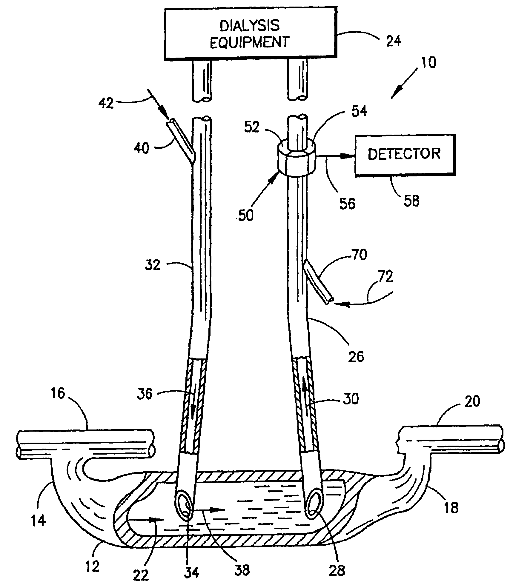
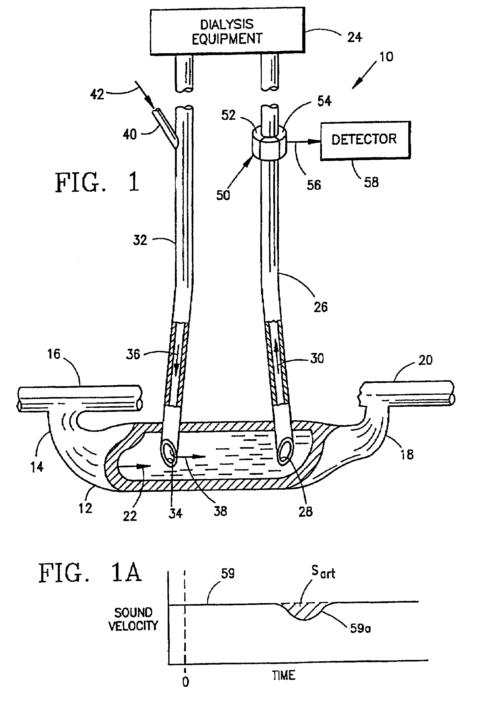
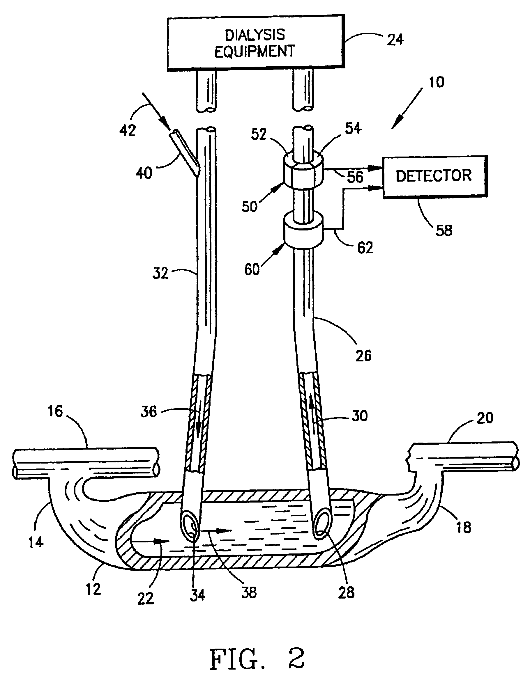
[0002]Dialysis is a process by which an artificial kidney replaces the function of a patient's kidney. Blood is removed from the patient's vascular system via an arterial line, is passed through a dialyzer and is returned to the patient via a venous line for normal circulation through the patient's vascular system. A majority of dialysis patients have an arterio-venous shunt implanted in a location having a high blood flow that simplifies the withdrawal of blood from the part that is closer to the arterial side of the shunt and the return of purified blood downstream of the withdrawal site, closer to venous side of the shunt. In some cases the shunt clots or stenoses and the resulting reduction in blood flow necessitates surgery that is costly and invasive for the patient. In the situation of low blood flow in the shunt or, if there is any other problem with the venous outflow, some part of the freshly dialyzed blood from the venous return line flows directly to the arterial withdrawal line where it is again filtered. If this undesired direct recirculation level is high enough, some amount of blood will be repeatedly refiltered and the rest of the patient's blood will not be sufficiently filtered to provide the patient with adequate dialysis.
[0006]The present invention avoids the problems encountered with previous methods and techniques by providing an accurate determination of shunt blood flow and undesired recirculation at lower cost.

Problems solved by technology

In some cases the shunt clots or stenoses and the resulting reduction in blood flow necessitates surgery that is costly and invasive for the patient.
If this undesired direct recirculation level is high enough, some amount of blood will be repeatedly refiltered and the rest of the patient's blood will not be sufficiently filtered to provide the patient with adequate dialysis.
This is very expensive and involves operation by highly-qualified professionals.
Measurements are therefore made only rarely and the onset of reduced flow, when treatment could be made without surgery can be missed.
This method requires blood samples from the patient, time from the nurses, and high laboratory costs.
Dialysis patients generally have lower hematocrit than the normal population and are at greater risk from losing blood, so this is not very satisfactory.

Method used


Image

  • Measurement of a blood flow rate in hemodialysis shunts
  • Measurement of a blood flow rate in hemodialysis shunts
  • Measurement of a blood flow rate in hemodialysis shunts

Examples


second embodiment

[0045]the invention is illustrated in FIG. 6, to which reference is now made. This embodiment provides a measurement of undesired recirculation of freshly purified blood while utilizing a “normal” connection of the dialysis equipment lines. Thus, in this embodiment the dialysis equipment 24 is connected to a patient's vascular system by way of shunt 12 and an arterial line 90 leading from inlet 92 to the dialysis equipment. Similarly, the equipment is connected to shunt 12 by venous line 94 which delivers purified blood from the dialysis equipment through outlet 96 in the shunt. The direction of blood flow in arterial line 90 is illustrated by arrow 98, and the direction of blood flow in venous line 94 is illustrated by arrow 100.

[0046]Although the outlet 96 is downstream from the inlet 92 in shunt 12, nevertheless such a “normal” connection can produce undesired recirculation of purified blood, as illustrated by arrow 102. Thus, purified blood can flow upstream in vein 12 and be pi...

first embodiment

[0049]If it is desired to avoid the need for a recalibration injection, a modified version of the device of FIG. 6 may be provided, as illustrated in FIG. 7. In this modification, an additional sensor 130 having a sound velocity source 132 and a sound velocity receiver 134 is provided on the venous line 94. The receiver 134 is connected by way of line 136 to the detector 118. The sensor 130 matches sensor 110 and is located downstream of the injection port 104, so that all of the blood from the dialysis equipment 24 as well as the indicator material 106 injected in port 104 will pass through sensor 130. The sensor measures the dilution curve in the arterial blood 100, and the same injection then produces a dilution in the flow 98 through arterial line 90. Sensor 110 detects the indicator material to provide a resulting signal to detector 118 from which the recirculation can be calculated in accordance with Equation 11, as outlined above with respect to the first embodiment and the v...


PUM


Abstract

The measurement of blood flow in a dialysis shunt is obtained by injection of an indicator material into a venous line leading from dialysis equipment to the shunt. The blood flow in an arterial line leading from the shunt at a location downstream of the venous line to the dialysis equipment is monitored by an arterial line sensor for the presence of the indicator material. A detector connected to the sensor provides a dilution curve in response to the presence of the indicator material and the blood flow in the shunt is calculated from the area under the dilution curve. The locations of the arterial and venous lines in the shunt can be reversed to obtain a measurement of blood recirculation from the venous line into the arterial line.

Description

CROSS-REFERENCE TO RELATED APPLICATIONS[0001]The present application is a division of U.S. Ser. No. 10 / 871,319 filed Jun. 18, 2004 now U.S. Pat. No. 7,297,280, which is a continuation of U.S Ser. No. 10 / 355,944 filed Jan. 31, 2003, now U.S. Pat. No. 6,926,838, which is a divisional of U.S. Ser. No. 09 / 734,352 filed Dec. 11, 2000, now U.S. Pat. No. 6,514,419 issuing Feb. 4, 2003, which is a continuation of U.S. Ser. No. 09 / 348,130 filed Jul. 2, 1999, now U.S. Pat. No. 6,210,591 issuing Apr. 3, 2001, which is a continuation of U.S. Ser. No. 09 / 010,697 filed Jan. 22, 1998, now U.S. Pat. No. 6,153,109 issuing Nov. 28, 2000, which is a continuation-in-part of U.S. Ser. No. 08 / 965,975 filed Nov. 7, 1997, now abandoned, which is a continuation of U.S. Ser. No. 08 / 305,953 filed Sep. 16, 1994, now U.S. Pat. No. 5,685,989 issuing Nov. 11, 1997, each of which is expressly incorporated by reference.[0002]Dialysis is a process by which an artificial kidney replaces the function of a patient's ki...

Claims


Application Information

Patent Timeline
Patent Type & Authority Patents(United States)
IPC IPC(8): A61B5/026A61B5/0275A61B8/06A61M1/16A61M1/36
CPCA61B5/0275A61M1/3653A61M1/3663A61M1/367A61M1/3658A61M1/16A61M1/3669A61M1/3655A61M1/3623
Inventor KRIVITSKI, NIKOLAI M.MACGIBBON, DAVID R.
Owner TRANSONIC SYST
Learn More